Se rendre au contenu
FPD.DEV FPD.DEVL’avenir du développement des écrans et des systèmes
  • Services
  • Produits
  • Formation
  • Partenaires
  • Vidéos
  • Planifier une consultation gratuite
  • Se connecter
  • 0
  • 0
  • English (US)  Français  Deutsch  Español
FPD.DEV FPD.DEVL’avenir du développement des écrans et des systèmes
  • 0
  • 0
    • Services
    • Produits
    • Formation
    • Partenaires
    • Vidéos
  • English (US)  Français  Deutsch  Español
  • Se connecter
  • Planifier une consultation gratuite
  1. Tous les produits
  2. Displays
  3. IRF / Hot mirror, 45° incidence, 12.5 mm diameter / 12.5 mm diameter / 45° incidence
  4. Displays
Liste de prix: FPD.DEV Public Catalog - Request a Quote Liste de prix
FPD.DEV Public Catalog - Request a Quote
Liste de prix: FPD.DEV Public Catalog - Request a Quote Liste de prix
FPD.DEV Public Catalog - Request a Quote
IRF / Hot mirror, 45° incidence, 12.5 mm diameter / 12.5 mm diameter / 45° incidence

IRF / Hot mirror, 45° incidence, 12.5 mm diameter / 12.5 mm diameter / 45° incidence

(0 avis)

Visible-transmitting, infrared-reflecting mirror for 45° incidence. Diameter 12.5 mm; thickness 1.10 ±0.20 mm. Average transmission exceeds 85% over 400–690 nm and average reflectance exceeds 95% over 750–1125 nm. No NVIS qualification is implied.

Application development required. Final configuration is established through a reviewed drawing and specification.

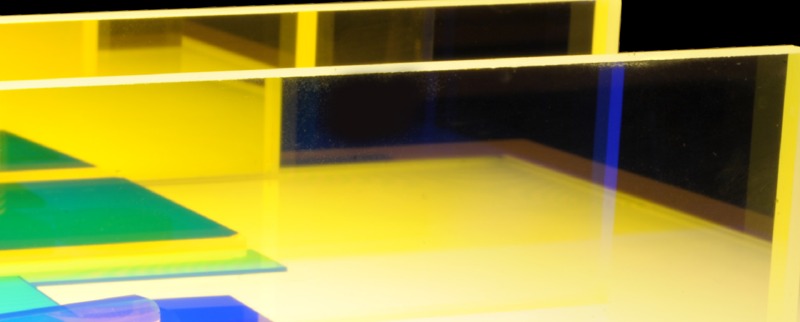
Representative filter-material photograph; supplied shape, color and construction depend on the selected design.

Save products to your Interest List to share your requirements, or contact us about this product.

Contactez-nous
Add this product to INTEREST LIST
Prix
Terms and Conditions

Référence interne: IRF-03025-00

Application and configuration

Infrared-control materials can be integrated near LEDs as chips, strips, caps or formed rails, or placed elsewhere in the optical path as the design permits. The material, LED and backlight geometry are selected together for the required visible output and infrared suppression.

Define the optical specification

Specify visible passband and minimum transmission, cutoff wavelength and its definition, transition width, blocked wavelength range and maximum transmission or optical density. Include source spectrum, temperature, angle-of-incidence range and polarization. Absorbing materials change response with thickness; interference coatings change response with incidence angle.

Visible and infrared bands

This reference passes visible light across 400–690 nm and reflects infrared across 750–1125 nm under the stated band-average limits. Route rejected light safely within the assembly. A hot mirror alone does not establish compliance with an NVIS requirement.

Specified band-average transmission and reflection at 45° incidence; no transition curve or pointwise blocking limit is implied.

Custom chip, strip or substrate drawing

Define outline and tolerances, thickness, clear aperture, edge finish, holes or mounting features, coating face and orientation. Include bonding or retention method, LED clearance, light sealing, thermal limits and inspection requirements. For caps and formed rails, define the complete LED envelope and paths around the filter.

NVIS integration

Class A or B requirements and output-color designations are separate inputs. Verify spectral radiance and color using the selected LEDs, drive levels, filters and complete backlight or display. These material references do not represent a released or qualified NVIS assembly.

From reference to a controlled part

Start with the application and available space. Develop a drawing with custom dimensions and performance specifications, review the proposed configuration, and evaluate samples where needed. Record the approved drawing revision and acceptance criteria for the supplied part. Availability and final configuration are confirmed during quotation.

Application data

Configuration-specific spectral, mechanical and electrical data is reviewed with the proposed drawing. Use Contact Us or add this reference to the Interest List to identify the application and requested format.

Backlight optics family · Browse related materials

Avis client :

Ingénierie des écrans axée sur le LCD Nous travaillons principalement avec les écrans LCD, notamment les technologies IPS, FFS, VA et autres, en intégrant des améliorations optiques, des interfaces tactiles, des rétroéclairages et l’électronique associée. Nous évaluons également d’autres technologies d’affichage lorsqu’elles conviennent à l’application.

Explorer l’optique LCD avec OpticalOracle™

Abonnez-vous à la newsletter FPD.DEV

Recevez par e-mail des articles sur les écrans et les systèmes embarqués, des analyses sur l’IA en périphérie, des mises à jour d’outils et des actualités produits.

Thanks for registering!

S’abonner

En vous abonnant, vous acceptez de recevoir la newsletter FPD.DEV. Vous pouvez vous désabonner à tout moment. Consultez notre Politique de confidentialité.


FPD.DEV
L’avenir du développement des écrans et des systèmes

  • Nous contacter


  • Politique de confidentialité


Nous contacter

Exploité par Colabmo · Qualité, opérations et Accompagnement ERP.


Politique relative aux cookies

Copyright © 2026 Colabmo ​ ​
Powered by Colabmo
Propulsé par Colabmo

Essential cookies support website functions. With your permission, Google Analytics measures visits and Microsoft Clarity records masked interactions, heatmaps and session replays on approved public pages. Optional embedded features may also contact their providers. These providers receive usage and device data; Microsoft may use data for its own purposes, including advertising. You can reject optional services and change your choice later. Cookie PolicyPrivacy Policy

Allow all optional cookies Only essential cookiesManage choices