Practical engineering guide · Updated 8 October 2026
DO-160 testing for aircraft displays
Plan the evidence from panel and optical stack to complete display system and aircraft installation.
A display can survive a cold soak yet respond too slowly to be useful. It can show a perfect image on the bench and reset during an aircraft power transfer. It can pass vibration in one fixture but fail when supported differently. A useful qualification plan connects the environment, the tested configuration and the display behavior the crew needs.
This guide covers display panels, optics, touch interfaces, controllers, power electronics, enclosures, mounting, cooling and connecting cables. Remote sensors and radar hardware are outside scope. The companion course chapter on test boundaries explains how to allocate evidence without assuming that a component report qualifies the finished system.

Start with three test boundaries
Component or subassembly. Characterize the LCD or OLED panel, backlight, optical bond, cover glass, touch sensor, driver boards, flex circuits and connectors under the conditions they actually experience. Measure cold response, hot luminance, uniformity, touch behavior and power demand. Look for bond separation, moisture effects, connector intermittency and stress caused by support or thermal expansion.
Component testing is most valuable early, when design changes are inexpensive. A sealed display’s internal panel does not necessarily receive the external water exposure. Conversely, its internal temperature can exceed cabin temperature. Supplier evidence should identify the part revision, electrical drive, fixture, exposure, measurements and acceptance criteria.
Complete display system. Qualify the production-representative assembly: panel, optical stack, electronics, power conversion, enclosure, seals, controls, cooling, mounts and cables. Include a separate display controller when it belongs to the supplied architecture. Apply disturbances at the appropriate equipment interfaces and observe the complete display function.
For example, a panel supplied from an internal 5 V rail may have useful temperature evidence. That evidence does not establish the complete display’s behavior at its aircraft 28 VDC input. The converter, protection, wiring and firmware can determine whether a power disturbance produces a reset, blanking or misleading information.
Installed display. Verify that the actual aircraft mounting, power, cooling, bonding, harness routing and viewing conditions satisfy the assumptions behind qualification. These are engineering boundaries, not separate DO-160 certification classes. Chapter 02 shows how to read a qualification claim critically and identify limits on evidence reuse.

Use the full suite as an applicability checklist
DO-160G has 23 environmental test sections, numbered 4–26. Consider every section, select applicable categories and document exclusions. The equipment specification and intended installation determine the allocation; every display does not need every exposure.
| DO-160G sections | What to consider for the display | Course detail |
|---|---|---|
| 4–6: temperature/altitude, temperature variation, humidity | Startup, image response, optical stability, condensation and cooling. | Ch. 06–09: climatic tests |
| 7–8: operational shock/crash safety, vibration | Glass and equipment retention, resonance, intermittent image or control faults. | Ch. 11: shock and vibration |
| 9–14: explosion proofness, waterproofness, fluids, sand/dust, fungus, salt spray | Installation exposure, seals, materials, contamination and corrosion. | Ch. 09–12: exposure and applicability |
| 15–21: magnetic effect, power input, voltage spike, audio-frequency conducted susceptibility, induced signals, RF susceptibility, RF emissions | Aircraft power behavior, interference resistance and emitted noise. | Ch. 13–14: power and EMC |
| 22–26: lightning-induced transients, lightning direct effects, icing, ESD, fire/flammability | Coupling paths, exposed surfaces, discharge behavior and safety requirements. | Ch. 15–16: lightning/ESD; Ch. 12: icing/fire |
The table groups the full suite for planning. Chapter 03 explains each section and its display-specific concerns. Category letters have meaning within their own section; they are not a universal severity ranking. A report marked Category X does not demonstrate compliance for that condition. Record the applicability rationale separately.
Give temperature limits an operating state
−40 °C, −55 °C, +70 °C and +85 °C are familiar values, but they do not define one universal operating range. State whether each value means normal operation, short-time operation or unpowered ground survival. A display that survives +85 °C without power has not demonstrated a readable image at +85 °C.
Selected DO-160G Table 4-1 examples make the distinction concrete:
| Temperature condition | Category A3 example | Category F2 example |
|---|---|---|
| Operating low / high | −15 / +70 °C | −55 / +70 °C |
| Short-time operating low / high | −40 / +85 °C | −55 / +70 °C |
| Unpowered ground survival low / high | −55 / +85 °C | −55 / +85 °C |
These examples are not category recommendations. Installation, temperature-control and altitude assumptions also apply. A contract can specify an additional operating range, but it must explain its relationship to the chosen category and define the required performance.
Measure the relevant temperatures: chamber air, enclosure, panel and electronics are not interchangeable. Record stabilization, dwell, heater operation and cooling. At cold startup, check time to usable information and image response; at high temperature, check luminance, color, touch behavior and thermal protection. See Chapter 04 for typical limits and Chapter 06 for temperature and cooling tests.

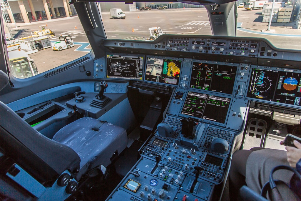
Photo: Cjp24 · CC BY-SA 3.0. Displayed at reduced size; no image edits.


Photo: Cjp24 · CC BY-SA 3.0. Displayed at reduced size; no image edits.

Temperature cycling: 5 versus 10 °C/min
Both rates appear in DO-160G Section 5: Category A specifies a minimum chamber change rate of 10 °C/min, Category B 5 °C/min, and Category C 2 °C/min. These letters are separate from the Section 4 temperature/altitude categories.
For a −40 °C to +70 °C transition, the temperature difference is 110 °C. Dividing by the ramp rate gives an ideal transition of 22 minutes at 5 °C/min or 11 minutes at 10 °C/min. Neither calculation includes stabilization or dwell, and neither predicts how quickly the optical stack reaches equilibrium.

Define endpoints, cycles, power sequencing, restart checks and monitoring. A cycle includes more than a one-way cold-to-hot transition. Combined Section 4/5 testing must retain the applicable requirements of both sections. The temperature-variation chapter develops the profiles and explains the distinction between chamber rate and equipment response.
Pressure, moisture and contamination
Decompression. A 65,000 ft equivalent endpoint is not a universal DO-160 requirement. In DO-160G §4.6.2, operating equipment starts at 8,000 ft equivalent pressure and transitions to the aircraft’s maximum operating-altitude equivalent within 15 seconds. The reduced pressure is held for at least 10 minutes, or as specified in the equipment specification.
If the contract calls for “explosive decompression,” define initial and final absolute pressure, transition time or profile, temperature, power state and required function. A much faster pressure collapse needs its own substantiation. Trapped optical cavities, vents, seals and glass retention deserve attention. Decompression is distinct from Section 9 explosion proofness, which addresses flammable atmospheres. See Chapter 08: altitude and decompression.
Humidity and water. Assess condensation, optical haze, leakage paths, touch behavior and corrosion. Identify which surfaces are exposed and whether cooling fans operate. A sealed front face does not establish protection at rear connectors or enclosure seams. Chapter 09 covers humidity, water and fluids.
Salt spray. The DO-160G Section 14 solution reference is 5 ±1% sodium chloride by mass at 35 °C. Category S alternates 24 hours of fog and 24 hours of drying, then repeats: 48 hours of fog within a 96-hour sequence before subsequent checks. Category T has a different sequence. A specification that merely says “48-hour salt fog” omits important conditions.
Inspect fasteners, coating edges, connector contacts, bonds and optical treatments against agreed criteria. Sand/dust can abrade surfaces or obstruct cooling; fungus assessment depends on actual materials. Chapter 10 develops these exposures, while Chapter 12 addresses explosion proofness, icing and fire/flammability applicability.
Fixed-wing and helicopter vibration
Aircraft type, installation zone and mounting determine vibration selection. Fixed-wing equipment may require standard or robust vibration under its specification, with separate abnormal-condition testing where applicable. Helicopter equipment follows the applicable robust approach; rotor-related frequencies and installation location are central to selecting the method.
A single overall g value cannot describe a vibration spectrum. Record frequency content, levels, duration, axes, resonance/endurance stages, mounting hardware and harness restraint. A rigid laboratory fixture does not by itself establish the behavior of a flexible instrument panel. Verify the installed bracket and support assumptions.
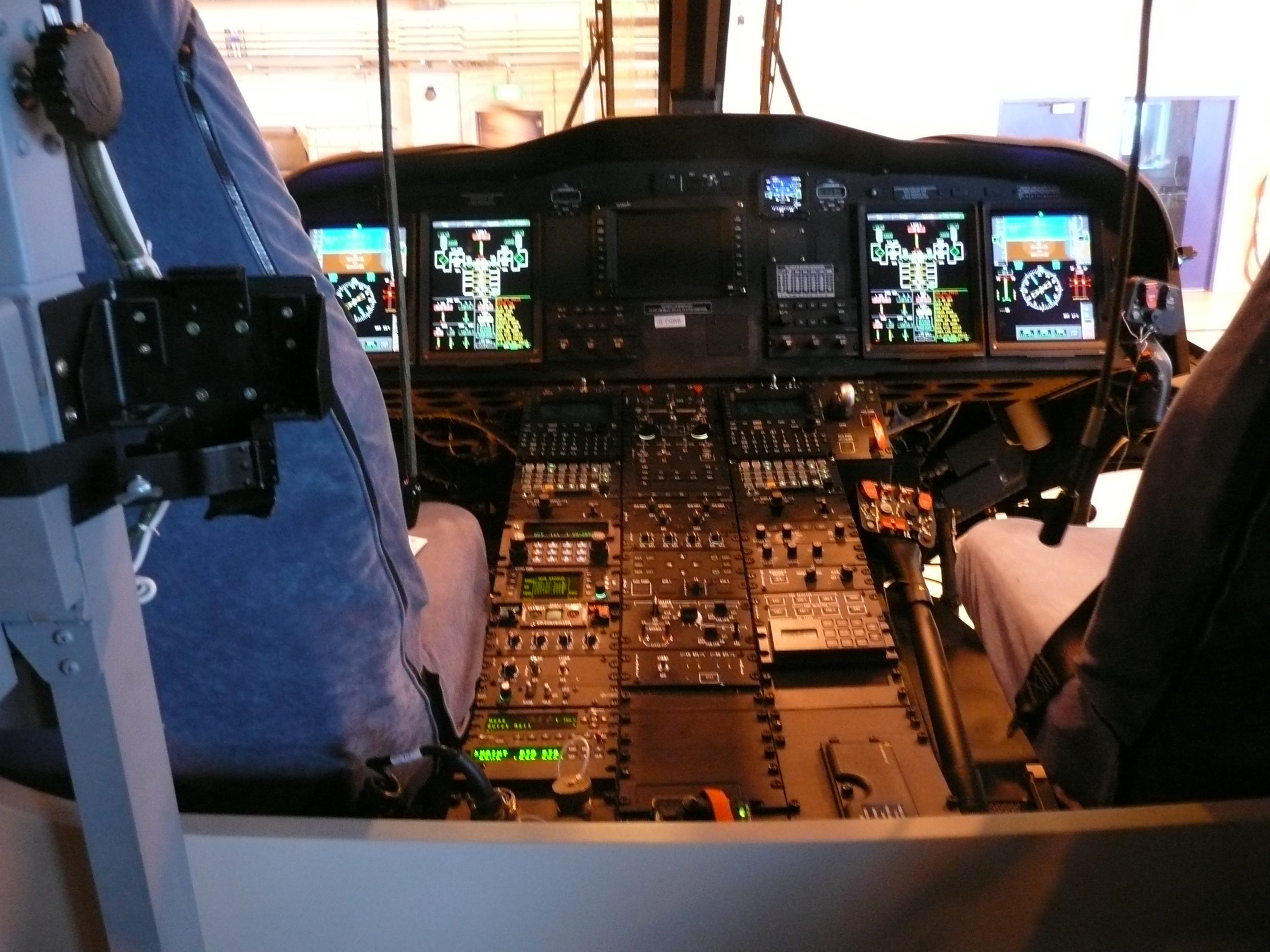
Photo: Terry Whalebone · CC BY 2.0. Displayed at reduced size; no image edits.

Monitor changing imagery, active links and controls during the required stages. A brief connector interruption or frozen frame may disappear before inspection. Keep operational-shock performance separate from crash-safety retention: remaining attached during a crash load is a different requirement from maintaining a usable image during normal operation.
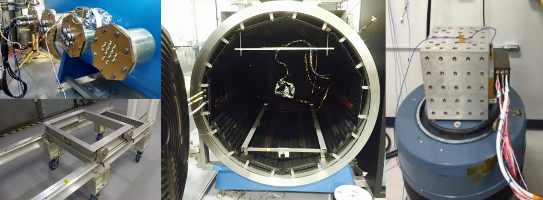
Photo: NASA Goddard Space Flight Center / Engineering and Technology Directorate · NASA imagery; generally not subject to US copyright. Displayed at reduced size; no image edits.
Chapter 11 compares fixed-wing and helicopter vibration methods, including known- and unknown-frequency approaches. A fixed-wing test report does not automatically qualify the same display for a helicopter.
Power, EMI/EMC, lightning and ESD
Apply aircraft power tests to the complete display’s aircraft interface. Exercise applicable normal and abnormal supply conditions, interruptions and transfers, then observe startup, blanking, resets, recovery and data validity. Backlight, heater, processor and touch-controller states can change both power demand and susceptibility. Chapter 13 explains power-input and related tests.
For EMC, distinguish interference generated by the display from its response to interference. Clocks, high-speed links, switching supplies and backlight PWM can produce emissions; cables and apertures can provide coupling paths. Use representative enclosures, shields, bonds, harnesses and terminations. There is no blanket helicopter RF severity multiplier.
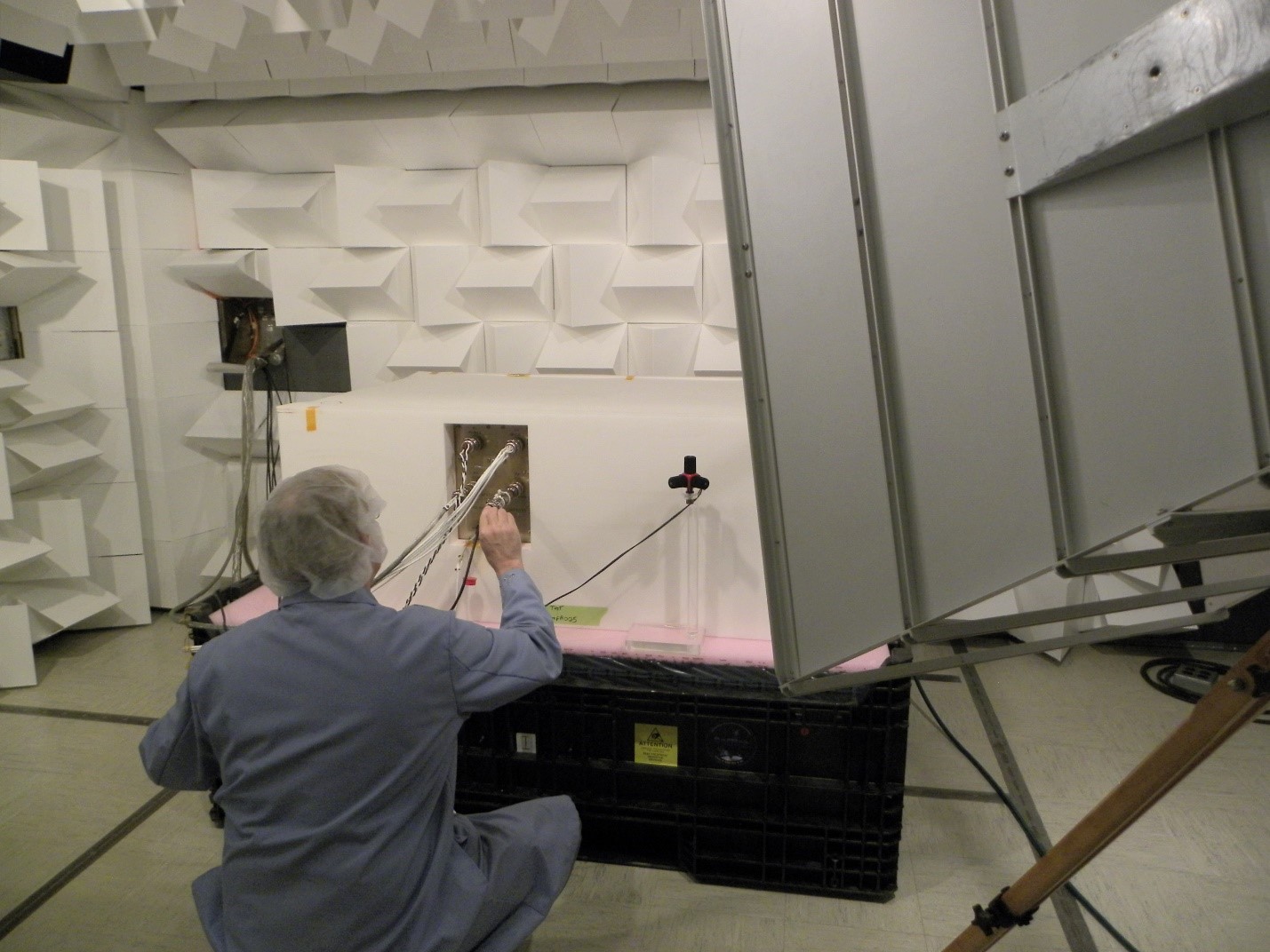
Photo: NASA Glenn Research Center · NASA imagery; generally not subject to US copyright. Displayed at reduced size; no image edits.
Record the complete categories, frequency ranges, modulation, levels and applicable curves. Thermally worst operation may differ from the noisiest or most sensitive mode. A moving counter, controlled input changes and synchronized observation help detect corruption and freezes that a static logo would conceal.
Connect equipment RF and lightning evidence to the aircraft HIRF and lightning compliance approach where applicable. Treat induced lightning transients, direct effects and ESD as distinct allocations. See Chapter 14: EMC, Chapter 15: lightning and Chapter 16: ESD.
Close the installation assumptions
Installed verification normally closes the equipment evidence against the aircraft configuration rather than repeating the whole chamber suite onboard. Check mounting and retention, ventilation, local heating, voltage at the display, returns, bonds, shield terminations and harness routing.
Evaluate actual eye positions, reflections, viewing angles, day/night dimming and control reach. Where specified, include eyewear, NVIS, gloves and operation under relevant vibration. Exercise required power transfers, input-loss indications and display reversion. Ground or flight evaluations, analysis and additional equipment tests follow the accepted compliance plan. Chapter 17 provides the installation checklist.
Buy reviewable evidence in the testing contract
“The display shall meet DO-160” is incomplete. Connect the equipment specification and interface-control documents to an environmental qualification matrix, approved procedures and report deliverables. State document precedence and any additional customer performance requirements.
A practical statement of work should settle these items before laboratory time is booked:
- Basis and scope: exact standard revision and changes, sections, categories, curves, waveforms, exclusions and responsibility for installation compliance.
- Test configuration: part and serial numbers, hardware/software revisions, optical stack, enclosure, cables, mounts, cooling and simulated inputs.
- Performance: numeric criteria, measurement conditions, monitoring, permitted degradation and recovery, plus checks before, during and after exposure.
- Test articles and sequence: sample allocation, accumulated exposures, destructive tests, spares, fixtures and permitted combined tests.
- Control and competence: procedure approval, relevant laboratory capability, calibration, any required accreditation scope, witness points and conformity arrangements.
- Anomalies and changes: stop/retest authority, recorded failures, corrective actions, regression scope and supplier change notification.
- Deliverables and commercial terms: as-run procedures, raw data, plots, photographs, configuration evidence, anomaly history, final reports, Environmental Qualification Form, installation limits, data-use rights and retest costs.
“No damage” is rarely a sufficient display criterion. Define time to usable information, luminance, image response, allowable flicker, touch accuracy, data-validity indication and recovery. Specify how an observation becomes a pass or failure before the test begins. The Environmental Qualification Form summarizes coverage; it does not replace the reports.
For example, require each test result to identify the agreed matrix row, tested configuration, operating mode, acceptance criterion and supporting data. A pass/fail certificate alone cannot answer why a result applies to a changed optical bond, replacement panel or longer aircraft harness.
Chapter 05 develops measurable criteria; Chapter 18 builds the matrix; Chapter 19 provides contractual detail and example wording; Chapter 20 covers changes and retests.
Standards and scope
This guide uses DO-160G section numbering and selected examples; confirm the edition and changes required by your program. FAA AC 21-16G describes an acceptable environmental qualification approach, not a blanket equipment or installation approval. Environmental qualification does not establish service life. Consult RTCA’s standards and supporting guidance and the accepted program requirements for the governing procedures.