01 / Adapt
FFC / FPC breakouts
Bring fine-pitch flex connections out to solder pads or standard 2.54 mm headers for probing and prototype wiring.
Browse flex breakouts →Products / Cables & connectors
Bring touch panels, displays, sensors and controllers together. Start with an FFC / FPC breakout for the bench, or work with FPD.DEV on quick-turn custom cables and small-run harness assemblies.
01 / Adapt
Bring fine-pitch flex connections out to solder pads or standard 2.54 mm headers for probing and prototype wiring.
Browse flex breakouts →02 / Wire
Connect to jumper leads, ribbon headers or screw terminals. Check whether headers are fitted or require soldering.
Browse header adapters →03 / Build
Define connector mates, pin mapping, length, shielding and test requirements for a repeatable cable or harness.
Explore custom assemblies →Prototype connections
Use these adapters to reach touch electrodes, low-speed control signals and flex connections. Select the physical connector and electrical pin map together.
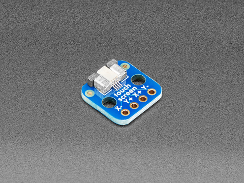
Access the four resistive touch electrodes on a small breakout board.
Fitted FPC connector; 2.54 mm solder connections
View ELC-03224-00 →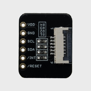
Bring a compatible capacitive touch controller tail out to individual prototype connections.
Fitted FFC connector; 2.54 mm through-holes
View ELC-03225-00 →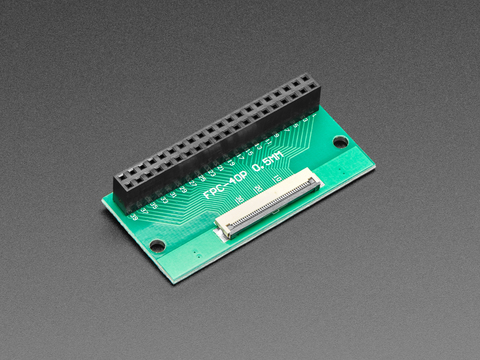
Connect a forty-way flat-flex cable to a standard dual-row header.
Fitted FPC connector and straight 2 × 20 female socket at 2.54 mm
View ELC-03231-00 →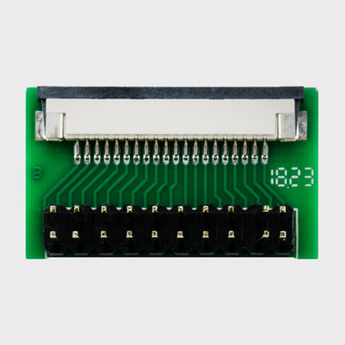
Connect a twenty-way 1.0 mm flat-flex cable to a dual-row header.
Fitted FFC connector and 2 × 10 header at 2.54 mm
View ELC-03234-00 →These are passive connection products. The listed pitch describes the flex connector or footprint unless noted. Bare PCBs need a separately selected connector and assembly.
| Product | Pitch | Bench connection |
|---|---|---|
| 4-Pin 0.5 mm Resistive Touch FPC BreakoutELC-03224-00 | 0.5 mm | Fitted FPC connector; 2.54 mm solder connections |
| 6-Pin Capacitive Touch FFC BreakoutELC-03225-00 | Confirm mating flex | Fitted FFC connector; 2.54 mm through-holes |
| 4–10 Pin 0.5 mm FPC Adapter PCB — Bare BoardELC-03226-00 | 0.5 mm | Bare PCB; 2.54 mm through-holes |
| 26-Pin 0.5 mm FFC Breakout BoardELC-03227-00 | 0.5 mm | Fitted FFC connector; 2 × 13 through-holes at 2.54 mm |
| 30-Pin 0.5 mm FFC Breakout BoardELC-03228-00 | 0.5 mm | Fitted FFC connector; 2 × 15 through-holes at 2.54 mm |
| 40-Pin 0.5 mm FFC / FPC Breakout BoardELC-03229-00 | 0.5 mm | Fitted bottom-contact, front-flip connector; 2.54 mm holes |
| Up-to-50-Pin 0.5 mm FPC Adapter PCB — Bare BoardELC-03230-00 | 0.5 mm | Bare PCB; 2.54 mm header pads |
| 40-Pin 0.5 mm FPC to 2 × 20 Female Header AdapterELC-03231-00 | 0.5 mm | Fitted FPC connector and straight 2 × 20 female socket at 2.54 mm |
| 22-Pin 0.5 mm DSI / HSTX FPC BreakoutELC-03232-00 | 0.5 mm | Fitted FPC connector; labeled header pads |
| 16-Pin 1.0 mm FFC Breakout BoardELC-03233-00 | 1.0 mm | Fitted FFC connector; 2 × 8 through-holes at 2.54 mm |
| 20-Pin 1.0 mm FFC to 2 × 10 Header BoardELC-03234-00 | 1.0 mm | Fitted FFC connector and 2 × 10 header at 2.54 mm |
| 40-Pin 2 × 20 Header to Screw-Terminal BreakoutELC-03235-00 | 2.54 mm header | Male 2 × 20 header; individual screw terminals; benchtop feet |
Availability, supplied parts and project pricing are confirmed by quotation. A matching pin count alone does not establish compatibility.
Long loose jumper wires can disrupt high-speed differential signals. Plan the pair routing, impedance, return paths, shielding and cable length for the interface. A passive breakout does not convert LVDS, eDP, DSI or other protocols. Use a purpose-designed interconnect and verify it with the target hardware; a DSI-specific adapter is not a universal LCD adapter.
Quick-turn custom cables
We support prototype cables, one-off development assemblies and small runs for displays, touch, sensors, power and embedded electronics.
Start with the mating components and a pin-to-pin map. We can help turn that into a cable drawing, connector and wire selection, routing details, labels and an agreed inspection and electrical test plan.
Quick-turn timing depends on connector availability, tooling, assembly complexity and design review. The quotation and approved drawing define the supplied configuration, tests, quantity and delivery schedule.
Have an existing cable? Share what works, what needs to change and which components it must mate with.
FPD.DEV ConnectorCanvas
Use our cable tool to select connectors, map connections and export a visual starting point for your project.
Build the connection map, label signals and review the connector views. Export SVG, PNG or PDF drawings and CSV connection data for discussion.
Share the design or quotation CSV with your requirements. We review mating orientation, ratings, component availability and production details before releasing an assembly drawing.
A passive adapter provides electrical access. A resistive touch panel still needs a suitable measurement circuit or controller; a capacitive panel needs its compatible controller and host interface. Confirm the panel pinout and voltage requirements.
Yes, where the adapter has a compatible fitted 2.54 mm header and the signals permit it. Some boards only provide through-holes and need soldered headers or wires. Loose jumper leads are not a general solution for high-speed display links.
FFC normally describes flat flexible cable with parallel conductors. FPC describes a flexible printed circuit that can include routed traces and components. Similar-looking connectors can differ in thickness, pitch and contact orientation, so use the mating specifications.
Yes. Share the connectors, pin map, length and quantity. We will review the assembly route, any tooling or minimum purchase quantities, and an achievable delivery schedule with you.