NVIS Fundamentals Engineering Short
What the Eye Sees Is Not What the Goggles See
Night Vision Imaging Systems, usually called NVIS, allow operators to see low-light scenes using night vision goggles and related imaging devices. In aircraft, helicopters, ground vehicles, marine systems, and defense equipment, the display and lighting environment must support the operator’s eyes while avoiding emissions that interfere with the night vision system.
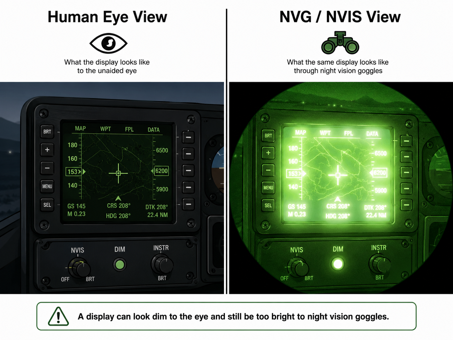
A display can look acceptable — even dim — to the unaided eye and still create a serious problem for night vision goggles. That is why NVIS compatibility is not just a brightness setting. It is a design, filtering, measurement, and system-integration problem.
The image above shows the core issue clearly:
what looks usable to the human eye may appear overly bright, bloomed, or distracting through NVGs.
Why “dim enough” is not the same as “night-vision compatible”
A standard display may appear acceptable during normal viewing and still fail NVIS requirements. The issue is not only visible brightness. NVIS compatibility depends on the way the complete display system behaves across visible and near-infrared wavelengths.
In practical terms, NVIS compatibility depends on:
- color
- luminance
- spectral radiance
- filtering
- dimming range
- the complete optical stack
MIL-STD-3009 establishes emission and compatibility requirements for aircraft lighting and display equipment intended for use with NVIS. It focuses on interface and performance requirements, not full lighting system design requirements.
The main idea
A display must do two things at the same time:
1. Remain readable to the human operator
The operator still needs enough visible luminance, contrast, color recognition, and uniformity to use the display effectively.
2. Avoid disturbing the night vision system
The display must limit unwanted energy in the spectral regions where night vision goggles are highly sensitive.
That is why a normal brightness or color measurement is not enough. NVIS evaluation often requires spectral radiance measurement and comparison against NVIS-specific limits.
Plain-language explanation
A night vision goggle is not simply seeing what your eye sees. It amplifies light in specific spectral regions. Some display emissions that seem weak to the eye can be very strong to the goggles.
This can cause:
Blooming
The display appears too bright or creates a glowing area in the NVG view.
Reduced outside-scene visibility
The operator loses contrast in the real-world scene.
Color or symbol confusion
Filtered colors may shift, dim, or become harder to distinguish.
False confidence
The display looks fine in normal viewing but fails NVIS radiance testing.
This leads to the most important engineering takeaway:
Key Lesson: NVIS Is a Stack-Level Design Problem
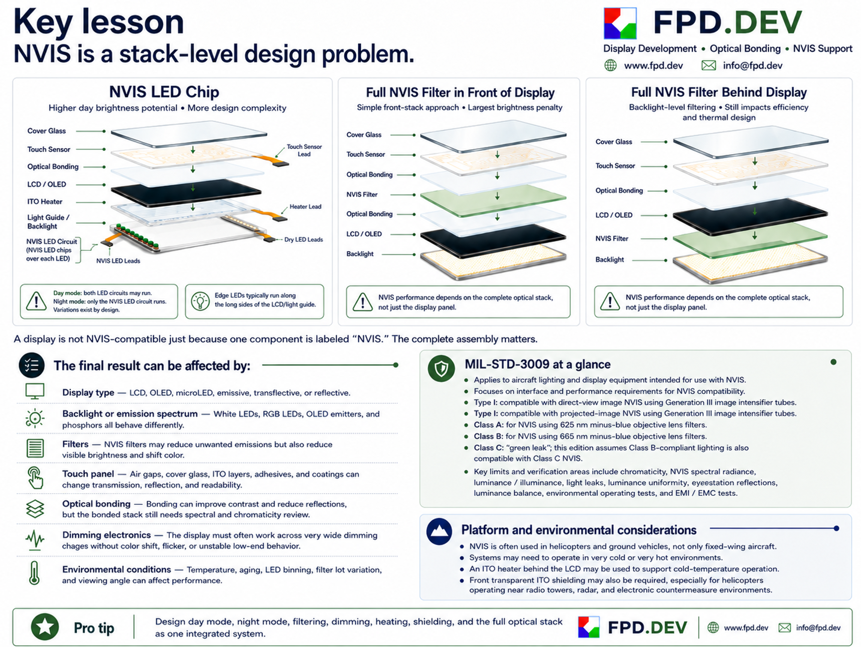
A display is not NVIS-compatible just because one component is labeled “NVIS.” The complete assembly matters.
The infographic above shows three common approaches:
- NVIS LED Chip
- Full NVIS Filter in Front of Display
- Full NVIS Filter Behind Display
Each approach can work, but each has tradeoffs in brightness, efficiency, complexity, uniformity, color shift, and thermal behavior. The correct choice depends on the application, platform, operating environment, and qualification requirements.
Common NVIS display stack approaches
NVIS LED Chip
This approach places NVIS filtering at the LED level, often in edge-lit displays where LEDs run along the long edges of the light guide.
A design may use:
- a day LED circuit with standard LEDs for higher visible brightness
- an NVIS LED circuit with filter chips over individual LEDs for NVIS-compatible night operation
In some designs, both circuits may run in day mode. In night mode, only the NVIS LED circuit runs.
Benefits:
Higher day brightness potential and less full-area optical loss.
Tradeoffs:
More complexity, more circuitry, more thermal considerations, and tighter control of LED binning and uniformity.
Full NVIS Filter in Front of Display
A full-area NVIS filter can be placed in front of the display, typically within the front optical stack.
Benefits:
Conceptually simple and easy to understand as a stack-level approach.
Tradeoffs:
Usually causes the largest visible brightness penalty because all emitted light must pass through the filter before reaching the operator.
Full NVIS Filter Behind Display
A full-area NVIS filter can also be placed behind the LCD and in front of the backlight.
Benefits:
Can reduce unwanted emissions at the backlight level.
Tradeoffs:
Still affects efficiency, power, thermal design, and final system performance. The full stack still has to be validated.
What affects the final result
The final result can be affected by many parts of the display system:
Display type
LCD, OLED, microLED, emissive, transflective, or reflective technologies all behave differently.
Backlight or emission spectrum
White LEDs, RGB LEDs, OLED emitters, and phosphors all produce different spectral outputs.
Filters
NVIS filters may reduce unwanted emissions, but they can also reduce visible brightness and shift color.
Touch panel
Air gaps, cover glass, ITO layers, adhesives, and coatings can affect transmission, reflection, and readability.
Optical bonding
Bonding can improve contrast and reduce reflections, but the bonded stack still requires spectral and chromaticity review.
Dimming electronics
The display often needs to operate over a wide dimming range without color shift, flicker, or unstable low-end behavior.
Environmental conditions
Temperature, aging, LED binning, filter lot variation, and viewing angle can all affect performance.
MIL-STD-3009 at a glance
MIL-STD-3009 applies to aircraft lighting and display equipment intended for use with NVIS. It establishes emission characteristics and interface/performance requirements for NVIS compatibility.
Types
Type I
Compatible with direct-view image NVIS using Generation III image intensifier tubes.
Type II
Compatible with projected-image NVIS using Generation III image intensifier tubes.
Classes
Class A
For NVIS using 625 nm minus-blue objective lens filters.
Class B
For NVIS using 665 nm minus-blue objective lens filters.
Class C
Associated with “green leak” NVIS. In this edition, lighting meeting Class B criteria is considered compatible with Class C NVIS.
Key verification areas include:
- chromaticity
- NVIS spectral radiance
- luminance / illuminance
- light leaks
- luminance uniformity
- eyestation or crewstation reflections
- luminance balance
- environmental operating tests
- EMI / EMC tests
Platform and environmental considerations
NVIS is often associated with aircraft, but it is also common in helicopters, ground vehicles, and other mission-critical systems.
These applications often need to operate in very cold or very hot temperatures, while also surviving vibration, shock, and challenging electromagnetic environments.
ITO heater for cold operation
An ITO heater behind the LCD may be used to support cold-temperature startup and operation.
Transparent ITO shielding
A front transparent ITO shield may also be required, especially in helicopters operating near:
- radio towers
- radar
- high-power transmitters
- electronic countermeasure environments
These added layers improve environmental performance, but they also become part of the optical stack and must be considered in the full NVIS design.
Pro tip
Design day mode, night mode, filtering, dimming, heating, shielding, and the full optical stack as one integrated system.
The best question is not:
“Is this one component NVIS-compatible?”
The better question is:
“Does the complete display assembly meet the required NVIS class, visible readability targets, environmental needs, and system-level integration requirements?”