Skip to Content
FPD.DEV FPD.DEVThe Future of Display Development
  • Services
  • Products
  • Learning
  • Schedule Free Consultation
  • Sign in
  • 0
  • 0
FPD.DEV FPD.DEVThe Future of Display Development
  • 0
  • 0
    • Services
    • Products
    • Learning
  • Sign in
  • Schedule Free Consultation
  1. All products
  2. Materials & Optical Bonding
  3. Glass
  4. IRF / Heat-absorbing filter glass, material 05
  5. Glass
Pricelist: FPD.DEV Public Catalog - Request a Quote Pricelist
FPD.DEV Public Catalog - Request a Quote
Pricelist: FPD.DEV Public Catalog - Request a Quote Pricelist
FPD.DEV Public Catalog - Request a Quote
IRF / Heat-absorbing filter glass, material 05

IRF / Heat-absorbing filter glass, material 05

(0 review)

Heat-absorbing glass with data referenced to 2 mm thickness. Internal transmission limits are 0.14 at 800 nm and 0.03 at 900 nm. Absorbed optical power heats the component.

Application development required. Final configuration is established through a reviewed drawing and specification.

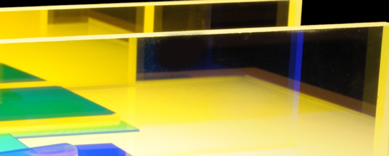
Representative filter-material photograph; supplied shape, color and construction depend on the selected design.

Pricing is available by quotation. Save products to your Interest List to request a quote for several items, or contact us about this product.

Contact Us
Add this product to INTEREST LIST
Price
Terms and Conditions

Internal Reference: IRF-03019-00

Application and configuration

Infrared-control materials can be integrated near LEDs as chips, strips, caps or formed rails, or placed elsewhere in the optical path as the design permits. The material, LED and backlight geometry are selected together for the required visible output and infrared suppression.

Define the optical specification

Specify visible passband and minimum transmission, cutoff wavelength and its definition, transition width, blocked wavelength range and maximum transmission or optical density. Include source spectrum, temperature, angle-of-incidence range and polarization. Absorbing materials change response with thickness; interference coatings change response with incidence angle.

Published upper limits on internal transmission at 2 mm. Absorption heats the glass; this plot does not establish NVIS suitability.

Custom chip, strip or substrate drawing

Define outline and tolerances, thickness, clear aperture, edge finish, holes or mounting features, coating face and orientation. Include bonding or retention method, LED clearance, light sealing, thermal limits and inspection requirements. For caps and formed rails, define the complete LED envelope and paths around the filter.

NVIS integration

Class A or B requirements and output-color designations are separate inputs. Verify spectral radiance and color using the selected LEDs, drive levels, filters and complete backlight or display. These material references do not represent a released or qualified NVIS assembly.

From reference to a controlled part

Start with the application and available space. Develop a drawing with custom dimensions and performance specifications, review the proposed configuration, and evaluate samples where needed. Record the approved drawing revision and acceptance criteria for the supplied part. Availability and final configuration are confirmed during quotation.

Application data

Configuration-specific spectral, mechanical and electrical data is reviewed with the proposed drawing. Use Contact Us or add this reference to the Interest List to identify the application and requested format.

Backlight optics family · Browse related materials

Customer Reviews


FPD.DEV
The Future of Display Development

  • Contact Us


  • Privacy Policy


Get in touch


Cookie Policy

Copyright © 2026 Colabmo ​ ​
English (US) Español
Powered by Colabmo

Text

We use cookies to provide you a better user experience on this website. Cookie Policy

Only essentials I agree