Clear glass
Preserves a broad range of image light. Untreated air/glass interfaces can add visible reflections; AR and optical bonding address those interfaces directly.
Learning / Display contrast glass
Compare clear cover glass, neutral gray and spectrally selective contrast filters. The goal is to preserve useful LCD light while reducing the ambient light reflected back toward the viewer.
Light from the LCD passes through a front filter once on its way to the viewer. Ambient light reflected by the LCD surface or other interfaces behind that filter passes through it on the way in and again on the way out. That second traversal creates an opportunity to reduce the reflected background more strongly than the image.
Preserves a broad range of image light. Untreated air/glass interfaces can add visible reflections; AR and optical bonding address those interfaces directly.
Attenuates the visible spectrum approximately evenly. At T = 0.70, image light becomes 70% and the internal ambient return becomes 49% of their unfiltered values.
Transmits useful display bands while attenuating less useful wavelengths. Its benefit depends on the LCD’s actual RGB output and the ambient spectrum, not the filter’s name alone.
The front surface is the exception. Light reflected at the viewer-facing air/glass interface has not traversed the absorbing glass. Bulk tint does not provide a double-pass reduction there. AR treatment and interface control remain essential.
For a simple neutral-gray model, keep front-surface reflection separate from reflection arising behind the filter:
LW and LB: emitted white/black luminance before the added filter. LR,int: ambient return from behind the filter before attenuation. LR,front: front-surface ambient reflection. All luminance values use cd/m².
Illustrative inputs: LW = 500, LB = 0.5, LR,int = 100 and LR,front = 5 cd/m². Ambient conditions, internal reflectance and front-surface contribution are held constant. The baseline is normalized to T = 1; real clear glass also has transmission losses.
| Case | Emitted white | Internal ambient return | Calculated ACR |
|---|---|---|---|
| Baseline, T = 1.00 | 500 cd/m² | 100 cd/m² | 5.73:1 |
| Neutral gray, T = 0.70 | 350 cd/m² | 49 cd/m² | 7.43:1 |
| Neutral gray, T = 0.50 | 250 cd/m² | 25 cd/m² | 9.26:1 |
Calculated examples, not measured product performance. The same 5 cd/m² front contribution is included in every ratio, along with the attenuated black level.
The image becomes dimmer, but its contrast against the reflected background improves in this example. This is not unlimited: a dark filter may make the image too dim, consume the brightness margin needed for temperature/aging, or lose its advantage when front-surface reflection dominates.
For example, with the same display and internal return but LR,front = 100 cd/m², ACR falls from 3.49:1 at T = 1 to 2.99:1 at T = 0.5. A darker window can therefore make the result worse. In zero ambient light, an ideal neutral filter attenuates emitted white and black equally and does not improve their intrinsic contrast ratio.
For a spectral filter, calculate emitted light using ∫ SLCD(λ) T(λ) V(λ) dλ and the internal ambient return using ∫ A(λ) Rint(λ) Tin(λ) Tout(λ) V(λ) dλ, with the appropriate photometric and geometric factors. Do not square an averaged visible-transmission number in place of the wavelength-by-wavelength calculation.
“Tri-notch” refers here to SCHOTT multibandpass glass: BG36, S8806A and S8851. Select the actual material by matching its wavelength-dependent transmission to the display’s RGB output. These grades have different, complex spectra; none should be represented by a generic idealized RGB curve. In optical terminology, a notch usually denotes a rejected band, so specify the glass grade and full transmission requirements.
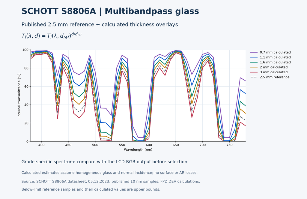
A well-matched filter can retain more useful RGB light than neutral gray for a comparable reduction in unwanted ambient return. It does not transmit all LCD light or remove all internal reflection. Ambient light within the passed RGB bands can still enter and return, and an unsuitable window can reduce a primary, shift white balance or limit gamut.
Bulk composition and finished thickness establish the spectral absorption. Thickness changes the transmission and color. Oblique rays have a longer internal path; surface reflections also vary with angle.
Interference coatings can create selective transmission on a substrate. Angular shifts, polarization and reflected stop-band light must be evaluated. A coated design has different manufacturing and reflection behavior from bulk absorbing glass.
A high-performance option, not a universal winner. Compare filtered display spectra, ambient contrast, retained luminance, color accuracy, viewing angle, thermal absorption, size, durability and cost. No single glass maximizes useful transmission and minimizes every reflection for every LCD.
Bulk spectral filter glass should not be specified as though it were ordinary, large-area float cover glass. Documented optical-filter production includes melting and casting, followed by grinding and polishing. The route below depends on the supplied blank and final drawing; a plate supplied near final thickness may not require slicing.
Select composition, spectral target, finished thickness and clear aperture. Confirm available blank dimensions, internal quality, environmental resistance and whether a bonded protective cover is needed.
Saw a thick blank into plates where required; cut near-net outlines from plate stock. Allow for kerf, chips and later material removal. Plan edge geometry and holes around the material’s processing limits.
Bring the blank toward thickness, flatness and parallelism. Control wedge and subsurface damage. Thickness tolerance is also a spectral tolerance for absorbing glass.
Polish optical faces and finish edges to the drawing. Inspect scratches, digs, chips, distortion and transmitted image quality. Clear aperture and cosmetic limits must be defined.
Evaluate AR, protective coatings and optional conductive layers. Qualify adhesives, cure conditions and stress. Strengthening processes are material-specific and must not be assumed suitable.
Verify spectral transmission at the finished thickness, surface reflection, dimensions, uniformity, appearance and environmental durability. Test the assembled LCD window under the intended illumination.
An absorptive first-order model is Ti(λ,d) = exp[−α(λ)d]. Internal transmission Ti excludes surface reflection; finished component transmission includes it. Use actual material data and tolerances for production decisions.
SCHOTT distinguishes contrast-enhancement, multibandpass and neutral-density families. The multibandpass grades below are identified in the 2026 portfolio; their individual datasheets provide the numerical spectra.
| Material family | Named grades | How to use it |
|---|---|---|
| Contrast enhancement | S8008G, S8802, S8808 | Starting candidates for display contrast evaluation; obtain full spectral data at the intended thickness. |
| Multibandpass | BG36, S8806A, S8851 | Separate filter family. Multiple transmission bands do not by themselves establish an RGB-matched display filter. |
| Neutral density | NG-series glasses | Compare wavelength neutrality, absorption and retained image luminance at the selected thickness. |
Use each grade’s actual spectrum, not an idealized three-peak curve. S8807 appears in the older 2018 overview; it is not represented here by a current numerical datasheet. Confirm the exact grade, melt/lot data, finished thickness, supply and manufacturable aperture for the project.
HOYA documentation also includes neutral-density, contrast and multiband filter categories. A specific currently available HOYA equivalent to an RGB-selective display filter has not been established here; compare actual data before specifying an alternative.
Glass products
Explore neutral gray, SCHOTT contrast-enhancement grades and SCHOTT multibandpass (tri-notch) glasses. The examples below are 1.1 mm; browse the catalog for other thicknesses and finishes.
Compare light, medium and dark absorption with the display’s brightness margin.
Uncoated examples. Catalog thicknesses: 0.7, 1.0, 1.1, 1.6, 2.0 and 3.0 mm.
Review each grade’s spectral curve and calculated thickness overlays.
Catalog finished-thickness options: 0.7, 1.1 and 1.6 mm, subject to fabrication review.
Tri-notch selections use actual named glass spectra. Compare each grade with your LCD’s RGB output.
0.7, 1.1 and 1.6 mm requested finished thicknesses. Published spectra and calculated thickness overlays on every product.
Uncoated and one-surface BBAR / AR versions are listed separately. Confirm cut size, finished thickness, coating orientation and spectral requirements by quotation.
Replacing clear glass changes more than color. Review mounting, weight, touch sensitivity, adhesive compatibility, thermal loading, viewing angle and the display’s calibration. Identify which reflecting layers are behind the filter: only those paths receive its full inbound/outbound attenuation.
Use OpticalOracle™ to explore relative interface and reflection effects supported by the model. Quantitative tri-notch selection additionally requires wavelength-resolved source, filter and reflection data; a single transmission slider is not a full spectral model.