Chapter 7 - Integration and Qualification Practice
Chapter 7 of 7 | FPD.DEV | Development edition A-P15
Integration and Qualification Practice
Installed performance and product claims; Test plans, uncertainty and anomaly records; Capstone trade study and evidence review. Use the reading-page controls below the presentation for explanations and worked practice.
This chapter currently has an animated slide presentation and detailed reading. Recorded narration will be added in a future update.
Open chapter with slide navigation and reading-page controls | Download chapter slides PDF (28 pages)
Slide narration transcript
Slide 123: Integration and Qualification Practice
FPD.DEV. The Future of Display and Systems Development. Welcome to Chapter 7, Integration and Qualification Practice. We will turn the measurements into a qualification package someone else can review. The chapter develops acceptance records, measurement decisions, specimen history and change control, then applies them to a constrained display design.
Slide 124: The installed display
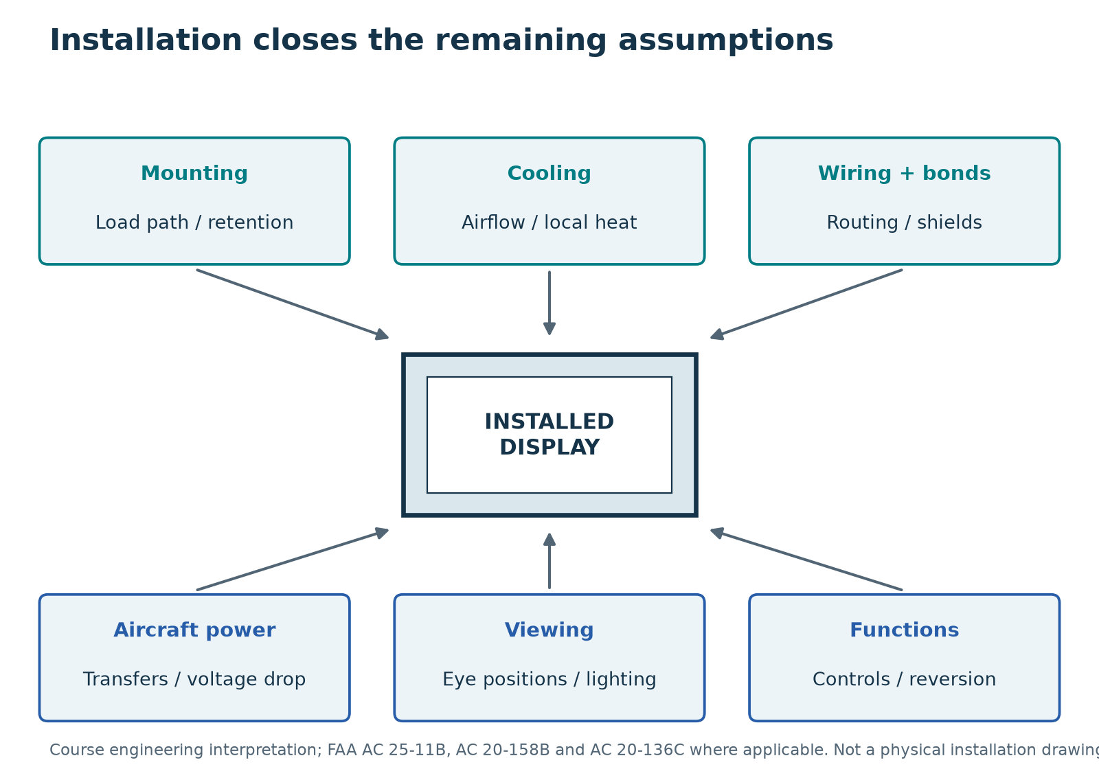
Installation verification closes the assumptions behind the equipment evidence. Check the brackets, ventilation, power, cable routing, bonds and shield terminations. Then evaluate the display from the intended eye positions with the relevant lighting, reflections, dimming and controls. A high on-axis contrast measurement at room temperature does not establish installed readability. Ground tests, flight tests, analysis and similarity follow the program's accepted compliance method. The transport-airplane display circular has a defined scope; rotorcraft programs need their applicable basis and guidance.
Slide 125: Display performance and crew use
Environmental capability is only part of a display specification. An invoked AS-eight-oh-three-four edition contributes airborne display-performance requirements. MIL-standard-three-thousand-nine addresses display and lighting emissions for use with NVIS. MIL-standard-fourteen-seventy-two supplies military human-engineering criteria. Determine which requirements actually apply. Connect optical, spectral, dimming and crew-use criteria to the acceptance plan, including checks during or after exposure when required. A temperature or vibration pass alone does not establish those separate performance claims.
Slide 126: Development assurance and installation
Software and electronic hardware require their applicable development-assurance evidence under the accepted program plan. DO-one-seventy-eight-C and DO-two-fifty-four address those scopes. The ARP-forty-seven-fifty-four and forty-seven-sixty-one families support system development and safety assessment. These activities help allocate functions, failure consequences and verification. Select the applicable revisions through the program basis. Environmental test results contribute to the overall argument, while interface-control documents, installed verification and approval requirements still need closure.
Slide 127: Qualification, production and service life
Environmental qualification belongs inside a wider verification program. Sunlight readability, UV aging, touch with gloves, cleaning abrasion, image retention and NVIS may need explicit additional requirements. Production acceptance checks the delivered units. Development stress tests and environmental screening serve other purposes. Passing a short environmental exposure does not establish ten years of service life. A duration claim needs a mission profile, relevant aging mechanisms and appropriate analysis or testing. Keep the purpose of each activity visible in the contract and evidence record.
Slide 128: Readability and spectral performance
A bright module measured normal to its surface does not describe every pilot's view through the installed cover. Establish the required viewing envelope, ambient illumination and dimming range for the application. Evaluate colour and information discrimination as well as luminance and contrast. Spectral filters, touch layers, EMI shields and heaters can all change the light reaching the observer. Where NVIS compatibility is required, use the applicable spectral criteria and operating modes rather than inferring compatibility from visible colour or low brightness. Measure the final optical assembly and preserve the conditions so an enhancement claim has a clear and repeatable scope.
Slide 129: Operating envelope and product claims
The product specification should say what the enhanced display actually does at each boundary. A cold ambient start with a defined warm-up period differs from immediate full performance. A temporary reduction in brightness at high temperature may be acceptable for one application and unacceptable for another. Define the permitted modes, duration and required indications, then verify them. Identify the assembly configuration, mounting, power and environmental conditions behind the claim. This makes it possible to offer capabilities beyond the original commercial module specification while acknowledging physical limits and qualification scope. Marketing language should follow those measured capabilities and the approved product requirements.
Slide 130: The test contract buys evidence
Two quotations can both say DO-160 and include very different work. One may buy chamber time and a certificate. Another may include procedures, raw traces, functional data, configuration records and anomaly disposition. Compare them against the same matrix before comparing price. Define article allocation, sequence, witness or conformity arrangements where required, and who can authorize deviations. Allocate retest costs and data rights. The commercial agreement should make the technical evidence deliverable clear without implying that a laboratory certificate resolves every aircraft requirement.
Slide 131: Closing a qualification matrix row
Return to the matrix we started in Chapter 1. A row is ready to close only when the evidence supports the current configuration and requirement. An earlier vibration report may be valid evidence, while credit for a changed bracket remains unresolved. Record that distinction. Trace the row to the procedure, raw data and report location. Include deviations and the accepted disposition. Carry forward limits on mounting, cooling, power and wiring so the integrator can preserve the demonstrated conditions.
Slide 132: A test-ready requirement record
A test-ready record connects the requirement to a measurement and a decision. For an illustrative hot-contrast row, name the assembly and mode, specify panel temperature and ambient illumination geometry, define white and black measurements, and state the minimum ratio with the decision rule. Link the procedure, instrument identification and uncertainty treatment. Add the result and the evidence location after execution. The adopted standard supplies the environmental method where applicable, while the product requirement supplies the functional acceptance criterion. Keeping those roles visible prevents a laboratory profile from being mistaken for a complete display performance specification.
Slide 133: Measurement uncertainty at acceptance
A measured value close to a limit needs a defined decision rule. Calibration uncertainty is one contribution, but optical alignment, source stability and repeatability can matter too. Agree how the laboratory will report uncertainty and apply it to the acceptance decision before the test. In an illustrative conservative rule, a contrast ratio of five point one with an expanded uncertainty of zero point three does not establish a minimum of five if acceptance requires the lower bound to exceed the limit. Other agreed rules can differ. State the rule explicitly and keep it separate from the environmental standard's prescribed test tolerances.
Slide 134: Test sequence and specimen history
Specimen history affects how a result can be interpreted. A seal already exposed to fluid, a connector repeatedly mated or an enclosure repaired after shock may behave differently from a new assembly. Establish the specimen allocation and test sequence using the applicable requirements and the agreed qualification plan. Record every exposure, adjustment and repair. If several specimens share the campaign, identify which configuration and serial number supports each matrix row. Avoid assembling a single clean pass narrative from different untracked units. The report must let a reviewer see both the required evidence and any limitations caused by sequence or specimen changes.
Slide 135: Changes and anomalies
A touch-controller change can affect emissions, ESD response, power loading and false-control behavior even when the image looks unchanged. Record the old and new configuration, identify affected mechanisms, and map them to requirements and existing evidence. Decide what can be credited and where testing is needed. If a cold-start failure receives a firmware fix, a room-temperature pass does not close the cold requirement. Retain the original failure and connect it to the correction, regression work and final disposition.
Slide 136: Worked example: changing the cover glass
Suppose you add bonded cover glass to protect an exposed polarizer. That may address a known moisture problem, but it also changes the product configuration. Record the glass, coatings, adhesive, thickness, mass and edge construction. Review optical transmission and reflections, thermal mismatch and heat flow, touch operation, and the mounting response to the added mass. Consider trapped voids and pressure equalization as well. This is a change-impact review, not a claim that every listed effect will require a full retest. Compare each affected requirement with the existing evidence, document the basis for any retained credit, and plan the missing verification on a representative assembly. Preserve the original configuration and results so another engineer can reconstruct the decision.
Slide 137: An anomaly record preserves the event
An anomaly record should begin with what happened, when it happened and the conditions at that moment. Record the specimen, software, operating mode and applied exposure. Keep an observation such as a two-frame flash separate from a proposed cause such as cell deformation. Preserve raw data, photographs and logs before repeating the test. During investigation, document each configuration change and its purpose. Once the cause and correction are understood, agree the affected retest scope and update the requirement matrix. A later successful run adds evidence, but it does not remove the need to explain and disposition the original anomaly.
Slide 138: A change-impact review across disciplines
Replacing a transparent heater can change more than cold performance. Its resistance and controller behaviour affect power demand. Its optical transmission and busbars affect the visible image. Its conductive structure can alter touch sensing and electromagnetic behaviour, and its bonding process can affect mechanical stress. Compare the old and new configurations against each relevant requirement and existing result. Document why an item remains covered or needs further evidence. A supplier's statement that the part is equivalent helps define the comparison but does not replace it. Close the review only when the resulting analysis, inspection or retest supports the revised assembly.
Slide 139: Capstone: the bonded touch display
Now apply the method. Our teaching display has a bonded cover, touch sensor, graphics processor, backlight, heater and metal enclosure. It uses nominal twenty-eight-volt aircraft power and an internal five-volt panel rail. The proposed location is a pressurized flight deck with four mounts and specified conduction plus local airflow cooling. These are scenario assumptions. The customer has temperature requests and an incomplete decompression statement, while power, vibration, RF and lightning allocations remain open. Your first job is to identify what you still need.
Slide 140: Capstone deliverables
Build the package in the same order as the course. Define the boundary and give missing inputs an owner. Screen all twenty-three sections and identify the information needed to finalize categories. Write cold-operation and temperature-variation outlines, preserving power state, stabilization and timing. Specify measurable display behavior and the monitoring needed to detect it. Finally, list the supplier deliverables and installation checks. The outcome is a reviewable plan, not a claim that testing has occurred. Pause here and complete the worksheets before viewing the response. In the mounting review, identify one thermal mismatch, one trapped-air volume and one vibration load path. Define how you will observe image quality and verify the proposed control.
Slide 141: Capstone review points
A strong response preserves the customer's temperature requests but checks their relationship to the selected category. It calculates the twenty-two-minute ideal ramp at five degrees per minute without calling that the full test duration. It asks why the decompression endpoint is sixty-five thousand feet and resolves the complete profile. It also refuses to invent missing power, RF, lightning or vibration categories. We, we keep those inputs open with named owners. The plan becomes stronger when its unresolved assumptions are explicit.
Slide 142: Second application: a helicopter
Propose the same display for an assumed unpressurized helicopter installation. Revisit the environment, mount and harness rather than carrying over the airplane assumptions. Isolators can improve mechanical behavior while changing the electrical bond path. Ask for the rotational-frequency basis and location-specific vibration information. Reassess EMC, HIRF, lightning, cooling and crew use. Your output is a comparison showing what evidence remains applicable, what additional work is needed, and which inputs are unresolved. This scenario is not a specification for the helicopter shown earlier.
Slide 143: Capstone: a military derivative
Now give the display an assumed military-aircraft application. Build the standards map before choosing tests. Consider tailored environmental exposures, equipment EMI, aircraft power and NVIS when the customer invokes them. Select one existing report and show exactly what it supports and what remains open. Then consider a military ground-vehicle derivative. Revisit power, vibration, mounting and crew use. Your deliverable is a justified comparison with owners for missing inputs, not a list of military-standard logos.
Slide 144: Capstone: a constrained design choice
For this capstone, assume a customer needs a readable cockpit display in bright ambient light, operation after cold soak, touch input and a fixed mounting envelope. The power budget limits heater and backlight demand. These are teaching assumptions rather than universal aviation requirements. Propose two optical and thermal configurations, then compare how each affects hot contrast, cold motion, power, EMC and mechanical behaviour. Identify the measurements needed to resolve the trade-off before choosing one. Record the uncertainties that remain and assign evidence to them. The exercise rewards a defensible decision and a coherent qualification plan, not simply the highest catalogue brightness.
Slide 145: Capstone review: what earns acceptance
Review the capstone as if you were accepting a supplier's qualification package. Can another engineer reproduce the test conditions and understand the decision? Does the hot-contrast claim include ambient illumination and panel temperature? Does the cold case address moving information and warm-up? Do the power and susceptibility cases include valid data and unintended commands? Check that changes to the optical stack connect to mechanical and electrical evidence. List unresolved items with an owner and a specific closure condition. A justified open item is preferable to an unsupported pass. Use the model response in the reading page to challenge your own reasoning.
Slide 146: Knowledge check
Pause and answer these three questions with a reason, not just yes or no. Does a panel temperature report cover the complete display? Does an unpowered survival result prove operation at that temperature? Does a radio-frequency emissions pass close aircraft HIRF compliance? For each one, name the missing boundary or evidence. The online course retains its fourteen formative questions with explanations. Use the results to revisit the corresponding matrix rows and capstone decisions rather than treating a score as a qualification certificate.
Slide 147: Knowledge check: the evidence gaps
The panel report can support its defined component scope, subject to a comparison. It cannot establish the complete aircraft interface or assembly response. The survival result supports its prescribed exposure and evaluation, not continuous operation. And emissions measures interference produced by the display, while susceptibility and aircraft HIRF involve different tests and installation evidence. The common lesson is to connect the claim to the function, exposure, configuration and supporting result. When one part of that connection is missing, keep the conclusion open.
Slide 148: Standards knowledge check
Pause and answer three questions. Can a military high-temperature storage pass automatically satisfy a DO-one-sixty operating requirement? Which standards distinguish equipment EMI from system electromagnetic effects? Does using the same chamber establish equivalent tests? Explain the missing evidence in each answer. Use the standards worksheet to trace a claim to the source, configuration, exposure and acceptance. The additional course questions provide feedback after you have made your own comparison.
Slide 149: Standards review: evidence and scope
The storage result leaves powered operation unproven. Four-sixty-one and four-sixty-four address equipment and system concerns respectively. And the same chamber can run very different profiles, configurations and checks. Test equipment is a means of applying and measuring the required exposure. It does not define the requirement. A sound comparison identifies supported evidence and remaining gaps, then records the program's acceptance of any proposed shared credit.
Slide 150: Chapter 7 complete
You have completed Integration and Qualification Practice. Use the supporting reading pages to work through the examples and record the evidence you would need for your display. Keep the requirements, configuration and evidence connected as the product changes. You are welcome to bring questions about your project to FPD.DEV. FPD.DEV. The Future of Display and Systems Development.
Reading pages
Page 15: Installed display and wider verification
Installed display verification
DO-160 Display Qualification | A-P13 — Development edition
Learning objective: Close installation assumptions without repeating the full environmental suite on the aircraft.
What remains to verify after installation
Installation work confirms that the assumptions behind qualification remain true. It is not normally a repeat of the whole chamber test suite on the aircraft.
For the display, the installation evidence should address:
- Mounting and retention. Verify brackets, fasteners, support stiffness, clearances and the load path. Assess changes from the laboratory fixture.
- Cooling and environment. Establish local temperatures, ventilation, heat from neighboring equipment, solar loading where relevant, and loss-of-cooling behavior. A cool cabin does not guarantee a cool display cavity.
- Power and wiring. Confirm voltage at the display, voltage drop, protection, returns, bonding, shields, connector terminations and harness routing against the qualified configuration and installation instructions.
- Electromagnetic compatibility. Conduct the required aircraft compatibility checks while observing display performance and unintended interference. The scope here remains the display and its installation, not qualification of neighboring equipment.
- Viewability and controls. Evaluate the actual eye positions, viewing angles, reflections, day/night dimming, control reach and any specified eyewear or NVIS compatibility.
- Display behavior. Verify startup, power transfers, display-to-display reversion where fitted, input-loss indications and recovery with the installed configuration. Use ground and flight evaluations where required by the compliance plan.
HIRF and lightning need a documented relationship between the installed exposure and equipment capability. Depending on the system and accepted compliance method, substantiation can combine equipment tests, installation data, analysis, similarity and aircraft-level testing. FAA’s current guidance includes AC 20-158B for HIRF and AC 20-136C for lightning protection. These do not make every aircraft-level test mandatory for every display. FAA AC 20-158B, FAA AC 20-136C.
Example installation verification record
| Assumption in equipment evidence | Installed check | Evidence |
|---|---|---|
| Cooling inlet remains unobstructed | Inspect clearances and substantiate operating temperatures | Identified installation drawing, survey and thermal results |
| Specified shield terminations and bonds | Inspect production routing and termination; measure where required | Harness configuration, bond records and approved limits |
| Required viewing envelope | Evaluate real eye positions, reflections and day/night settings | Geometry, lighting conditions, observations and measured performance |
| Power-transfer behavior is supported | Exercise allocated transfers with the installed configuration | Time-aligned power and display-event record |
Viewing is a system property
Reflections from windows and cockpit surfaces, viewing angle, sunglasses, display recess depth and adjacent lighting can change readability. A high room-temperature on-axis contrast number cannot establish installed readability in sunlight or at night. Include applicable dynamic behavior, dimming range, color coding and controls in the intended use.
Exercise
The installed bezel partially covers a vent, although the electronic unit is unchanged. Worked response: reopen the cooling assumption, assess thermal and functional consequences, and resolve the installation or qualification evidence. Configuration control includes the mounting environment, not only the supplier's electronics part number.
Use FAA AC 25-11B within its transport-airplane electronic-flight-display scope. Other aircraft or display roles need their applicable requirements and guidance. Ground and flight evaluations follow the accepted compliance plan; this course does not prescribe a universal flight-test program.
Installed checks for airplanes and helicopters
Plan representative aircraft operating conditions instead of repeating the laboratory suite onboard. The following are proposed planning items; the aircraft compliance plan determines what must be demonstrated.
- Mechanical and crew use: compare actual mounts, brackets, isolators and panel stiffness with the qualification assumptions. For helicopters, include the relevant rotor-speed and operating-condition range when evaluating image readability, touch targeting and physical controls. For propeller aircraft, consider the applicable engine/propeller operating range; jet installations have their own structural and abnormal-condition assumptions.
- Electromagnetic interactions: define the applicable transmitter states, receiver checks, electrical loads and power transfers. Observe both disturbance of the display and interference from the display into relevant installed functions. Use the actual shielding, returns and mount-bond arrangement.
- Exposure and mission: identify pressurization, doors-open operation where intended, dust/water exposure, solar loading, night operations and specified NVIS/eyewear/glove conditions. These depend on the installation and mission, not on a blanket airplane/helicopter rule.
- Evidence closure: list any unverified difference and its disposition. Ground or flight testing, analysis, similarity or additional equipment tests follow the accepted method; none is automatically replaced by the equipment report.
AC 25-11B addresses transport-airplane electronic flight displays. Use the applicable Part 27/29 rotorcraft requirements and guidance for a helicopter program rather than treating that airplane circular as a universal rotorcraft approval basis. FAA AC 20-158B and FAA AC 20-136C cover their stated airplane and rotorcraft compliance contexts.
Mounting evidence
Carry the verified mechanical stack into the installation record: module supports, fastener controls, gasket compression, thermal accommodation, isolator configuration, harness routing and retention. The Page 10 guidance in Chapter 4 is a design-review framework. Qualification evidence belongs to the actual configuration.
Connection to the standards map
Verify the invoked display-performance standard, aircraft interface-control documents and crew-use criteria. Where applicable, carry MIL-STD-3009 NVIS and MIL-STD-1472 human-engineering requirements into installed checks.
Additional verification and production acceptance
DO-160 Display Qualification | A-P13 — Development edition
Learning objective: Separate environmental qualification from optical performance, lifetime and delivered-unit acceptance.
Plan beyond DO-160 where the display requires it
Environmental qualification should sit beside the display’s broader verification program. Depending on the intended use, additional work may include sunlight and ambient-contrast measurements, solar heating, UV aging, touch operation with gloves or moisture, cleaning abrasion, impact resistance, NVIS compatibility, long-term image retention or burn-in, and reliability or life testing.
Customer specifications may also invoke optical measurement standards, military environmental/EMC requirements, ingress ratings or material fire tests. Name the exact editions, methods and acceptance criteria. Evidence from IEC, military or other tests may be useful, but equivalence to a selected DO-160 test needs a documented comparison; the standards are not interchangeable by label.
Qualification samples establish design evidence. Production acceptance tests check delivered units against defined requirements. Environmental stress screening and highly accelerated development tests serve different purposes again. State which activities the contract buys and what each deliverable proves.
The strongest display qualification program carries a clear argument from component capability to complete-system performance and then to the installed use. That argument starts with precise requirements, survives configuration changes, and ends with evidence another engineer can examine.
Allocate additional work deliberately
Create separate requirement rows for ambient contrast, glare, sunlight heating, UV exposure, touch with gloves/water, cleaning abrasion, image retention, NVIS and life claims as applicable. Name methods and numeric acceptance conditions; do not present these as universally covered by the DO-160 category string.
Development stress testing can expose weaknesses beyond the rated envelope. Environmental stress screening can address manufacturing defects. Production acceptance verifies delivered units against the agreed checks. Life or reliability claims require evidence appropriate to the claim, including assumptions and statistical interpretation. A small qualification sample surviving a short exposure does not establish a fleet failure rate.
Exercise
A qualification article passes the agreed thermal tests. The sales specification then claims ten years of service life. Worked response: the environmental result can contribute to the design evidence, but the duration claim needs its own basis: mission profile, aging mechanisms, duty cycle, maintenance, analysis and relevant testing. Do not equate chamber hours with service years without a justified model.
Connection to the standards map
The standards map on Page 04 in Chapter 1 distinguishes DO-178C/ED-12C software, DO-254/ED-80 electronic hardware, ARP4754 development and ARP4761 safety-assessment evidence. Add applicable AS8034, MIL-STD-3009 and human-engineering criteria to the verification plan.
Page takeaway
- Close differences between the installed arrangement and the assumptions in equipment evidence.
- Allocate additional performance, production and life claims to evidence appropriate to each purpose.
Supporting page images
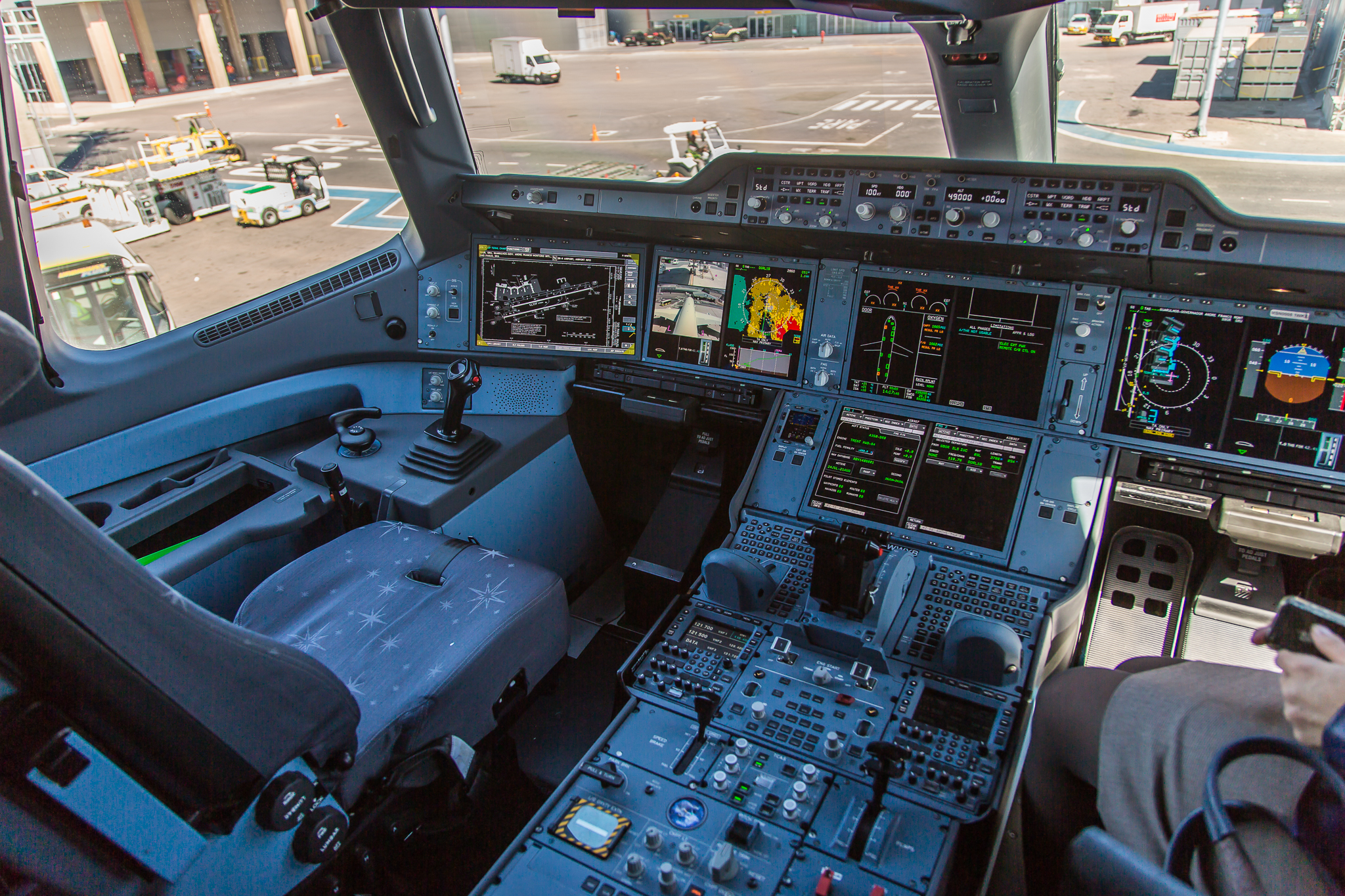
Photo: Joao Carlos Medau · Airbus A-350 XWB F-WWYB cockpit view · CC BY 2.0. Original image, displayed at reduced size.

Image: AlbertCahalan (Wikimedia Commons: AlbertCahalan~commonswiki) · Zone plate boys · CC BY-SA 3.0. Source image retained unchanged; displayed at reduced size.

Engineering application and worked evidence
The following examples develop the display mechanisms and evidence decisions. Numerical values are teaching assumptions, not universal DO-160 limits. Use the adopted procedure for exact test conditions and the product requirements for functional acceptance.
Readability and spectral performance
A bright module measured normal to its surface does not describe every pilot's view through the installed cover. Establish the required viewing envelope, ambient illumination and dimming range for the application. Evaluate colour and information discrimination as well as luminance and contrast. Spectral filters, touch layers, EMI shields and heaters can all change the light reaching the observer. Where NVIS compatibility is required, use the applicable spectral criteria and operating modes rather than inferring compatibility from visible colour or low brightness. Measure the final optical assembly and preserve the conditions so an enhancement claim has a clear and repeatable scope.
Basis: RTCA DO-160G, Section 4; FAA AC 25-11B; MIL-STD-3009 where adopted. Retained reference in 80 Reference Library/Aerospace. Display mechanisms, design responses and worked cases are FPD.DEV engineering teaching synthesis, not additional DO-160 requirements. Numerical examples are illustrative.
Operating envelope and product claims
The product specification should say what the enhanced display actually does at each boundary. A cold ambient start with a defined warm-up period differs from immediate full performance. A temporary reduction in brightness at high temperature may be acceptable for one application and unacceptable for another. Define the permitted modes, duration and required indications, then verify them. Identify the assembly configuration, mounting, power and environmental conditions behind the claim. This makes it possible to offer capabilities beyond the original commercial module specification while acknowledging physical limits and qualification scope. Marketing language should follow those measured capabilities and the approved product requirements.
Basis: RTCA DO-160G, Sections 3 and 4; authored product specification guidance. Retained reference in 80 Reference Library/Aerospace. Display mechanisms, design responses and worked cases are FPD.DEV engineering teaching synthesis, not additional DO-160 requirements. Numerical examples are illustrative.
Practice: A claim of extended temperature operation
Write the information needed to support a claim that an enhanced LCD operates below the original module ambient rating using a heater.
Model response and review points
State the complete assembly, external ambient limit, LCD temperature limits, power and heater configuration, warm-up period, performance during warm-up, required cold motion and touch behaviour, mounting and airflow. Include heater-control fault provisions as required by the system. Demonstrate the claimed assembly envelope while preserving the meaning of the original component rating. Distinguish tested performance from development targets.
Page 16: Test contracts and qualification evidence
Completing the qualification matrix
DO-160 Display Qualification | A-P13 — Development edition
Learning objective: Create traceability from requirement to test and installation limitation.
A matrix is an argument, not a checklist of ticks
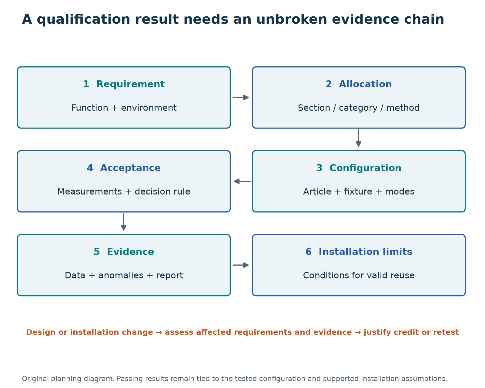
Each row should state what is required, why the environment applies, how the condition is represented, what performance is acceptable and where the evidence can be found. Keep applicability, planned method and completed evidence separate. “Planned” is not “passed,” and a report issued with unresolved deviations may not close the row.
| Field | Example teaching entry |
|---|---|
| Requirement and function | DISP-TEMP-01, usable image under allocated cold operation |
| Boundary | Complete display including cover, touch, PSU, enclosure and cables |
| Source and exposure | DO-160G Section 4 plus explicit customer temperature requirement |
| Category/subtest | To be selected from aircraft location; do not infer from temperature alone |
| Configuration | Part/serial/BOM/software list and representative fixture |
| Acceptance | Startup, image, controls and optical limits identified by requirement IDs |
| Evidence | Procedure revision, as-run data and report paragraph |
| Installation limit | Required cooling, power, mounting and harness assumptions |
| Status/owner | Proposed; aircraft environment input due from integrator |
Do not hide unresolved inputs
If maximum operating altitude or the power category is unknown, assign an owner and due point. A provisional category may be useful for quoting, but label it and state the cost/schedule consequence of change. A supplier cannot finalize every installation allocation from the display data sheet alone.
Allocate test articles
Multiple articles can be used where permitted, but respect sequence and cumulative-exposure requirements. Maintain an exposure history per serial number and record repairs, replacements and software changes. A report assembled from results on different hardware needs a clear representation and configuration argument.
Exercise
Your matrix says vibration passed, but the cited report tested an earlier mounting bracket. Worked response: keep the result as existing evidence, mark the current configuration credit unresolved and assess the difference. Close the row only with justified applicability or affected retesting. The report's pass word does not settle configuration relevance.
Deliverable
Create all 23 section rows, then expand the applicable sections into subtests. Add during/post/survival criteria, article allocation and installation constraints. Use a separate unresolved-input list to prevent empty fields being misread as intentional exclusions. The contract lesson shows how to make this matrix part of the purchased deliverable.
Add an aircraft application column
When a product serves both airplanes and helicopters, use separate application rows or clearly identified coverage rather than a single merged “worst case” category. Record aircraft/variant, propulsion or rotor configuration, display location, mount/isolator configuration, operational role and the source of each environmental allocation.
For vibration, record category, curve, zone, known-frequency inputs or unknown-frequency method, and any tailored-data basis. For EMC/HIRF, record the equipment categories separately from aircraft coupling/attenuation evidence and installed compatibility checks. Identify where one test supports several applications and what comparison justifies that credit. Use “unresolved—integrator input required” where aircraft data are missing.
Test contracts and supplier deliverables
DO-160 Display Qualification | A-P13 — Development edition
Learning objective: Write a statement of work that buys reviewable qualification evidence.
What to put in the testing contract
“The display shall meet DO-160” is a starting point for discussion, not a complete test specification. A practical purchase specification or statement of work connects the equipment requirements, environmental qualification matrix, test plan, procedures and report deliverables.
The document stack often extends beyond DO-160. For example, SAE AS8034 addresses airborne multipurpose electronic display performance, while an aircraft manufacturer’s equipment specification and interface-control document define the particular installation. Military contracts may invoke MIL-STD-810 for tailored environmental testing and MIL-STD-461 for equipment electromagnetic interference requirements. Where night vision imaging system (NVIS) compatibility is required, MIL-STD-3009 addresses aircraft lighting and display emission characteristics. Each document has a different role; select the applicable revision and requirements rather than adding a list of standards without a compliance plan. SAE AS8034, DLA MIL-STD-461, DLA MIL-STD-3009.
The following are recommended contracting topics. They are not all universal DO-160 requirements.
| Contract topic | What to specify |
|---|---|
| Applicable documents | Exact DO-160 revision and changes; customer specifications; applicable performance standards; installation requirements; document precedence and discrepancy resolution |
| Qualification matrix | Every section considered; applicability and rationale; selected categories, subtests, levels, curves, waveforms and methods; requirements satisfied; party responsible |
| Equipment boundary | Included panel, optical stack, touch hardware, controller, power supply, enclosure, cables and accessories; excluded items and simulated interfaces |
| Configuration | Part numbers, serial numbers, drawing/BOM revisions, firmware/software, manufacturing state, mounting and cooling; representation of variants and worst cases |
| Performance requirements | Numeric limits and functional criteria, their requirement IDs, measurement conditions, uncertainty decision rules, monitoring intervals and allowed recovery |
| Test articles | Quantity and rationale, allocation among tests, conditioning, accumulated exposure, destructive-test articles, spares and disposition after testing |
| Test arrangements | Fixtures, cable types and lengths, shielding, terminations, bonding, loads, input simulators, operating modes and support-equipment effects |
| Test sequence | Required order and dependencies; permitted combined tests; intermediate checks; treatment of repairs or configuration changes between tests |
| Laboratory and witnessing | Relevant capability, calibration and traceability; any required ISO/IEC 17025 accreditation scope; customer witness points and any applicable certification conformity arrangements |
| Deviations and failures | Who can authorize a procedure change, pause or retest; anomaly recording; root-cause work; corrective action; regression scope; acceptance authority |
| Deliverables | Plan and procedures, as-run records, measured data, plots, configuration evidence, calibration records, deviations, failure/retest history, final report and Environmental Qualification Form |
| Installation responsibilities | Supplier installation limits and instructions; integrator obligations for cooling, mounting, power, wiring and installed verification; responsibility for compliance submissions |
| Commercial responsibilities | Ownership and permitted reuse of data, access to raw results, record retention, schedule, included engineering support, retest costs and change pricing |
| Change control | Supplier change notification and impact assessment for panel, optical bond, touch controller, electronics, firmware, enclosure or harness substitutions |
Category letters are not a universal ranking. Select and interpret them within their own section, including any multi-character designations. “Higher category” is not a sufficient technical comparison. In DO-160G, Category X records that compliance was not demonstrated for that environmental condition; it is not a passing result or an automatic finding that the condition is irrelevant. Keep a separate applicability rationale.
A useful matrix row follows the chain:
Display requirement → environmental section and category → test configuration and method → acceptance criterion → evidence → installation limitation.
The Environmental Qualification Form summarizes the environmental coverage; it does not replace the detailed reports. Its value depends on traceability to the tested equipment and supporting evidence. RTCA Environmental Qualification Form.
Example contract wording
The following is an adaptable clause, not a complete qualification specification:
The supplier shall demonstrate that the display configuration identified in the approved configuration list meets the performance requirements referenced by the agreed Environmental Qualification Matrix under the DO-160 revision, sections, categories, methods and conditions stated in that matrix. The matrix shall identify the treatment of every environmental section, including the basis for exclusions and any proposed credit from existing evidence. Before qualification testing, the parties shall agree the test plan, procedures, operating modes, monitoring, acceptance criteria, test-article allocation and required conformity or witness arrangements. Procedure deviations, configuration changes and failures shall be recorded and dispositioned under the agreed change process. Retesting shall not erase the original results. The supplier shall deliver the as-tested configuration record, as-run procedures, results and supporting data, anomaly and retest records, final qualification report, Environmental Qualification Form, and installation limitations. Installation compliance responsibilities shall be allocated separately in the statement of work.
Quote comparison exercise
Quote A includes chamber time and a pass/fail certificate. Quote B includes procedures, article configuration records, raw traces, performance data, anomaly disposition and an Environmental Qualification Form. They may cover different work even if both say DO-160. Compare each quotation against the same matrix, acceptance requirements, witness arrangements and deliverables before comparing price.
Avoid open commercial assumptions
State who pays for fixture redesign, failed setup attempts, equipment repairs, customer changes and retests. Define what laboratory time and engineering analysis are included. State data-use rights separately from permission to redistribute licensed standards. Neither a test report purchase nor a training-course subscription automatically grants republication rights to standards figures.
Contract review output
Prepare a one-page list of unresolved technical inputs and a deliverable schedule. Mark approval or witness hold points only where the program actually requires them. If a certification conformity arrangement applies, identify who arranges it and when. A laboratory's accreditation alone does not resolve every program-specific conformity or acceptance obligation.
Contract addendum for fixed-wing and helicopter applications
The purchase specification should identify each intended aircraft application and the extent of qualification credit being purchased. The following adaptable clause supplements the general statement of work:
The supplier shall identify the fixed-wing and helicopter applications covered by the proposed environmental evidence, including aircraft type, equipment location, installation limitations and as-tested mounting and harness configuration. Vibration evidence shall identify the DO-160 category, applicable curve/zone, frequency basis, operating conditions, performance and endurance stages, and resonance/control records. Any unknown-frequency helicopter method or tailored profile shall state its permitted coverage and agreed basis.
The qualification matrix shall separately identify equipment electromagnetic tests, aircraft HIRF and lightning substantiation responsibilities, and installed compatibility checks. Changes in mounting isolation, bonding, cable length, shielding, termination or aircraft application shall receive a documented impact assessment before existing evidence is credited.
Request a coverage comparison if a supplier offers a single “airplane and helicopter qualified” report. Require the integrator to provide the missing aircraft allocations and define who closes each installation assumption. Do not buy an unsupported claim that a larger overall vibration g value or one higher RF field value covers every other profile.
Connection to the standards map
List the edition and tailored requirement for every invoked standard. Define which test record supports which requirements and who accepts any proposed qualification credit.
Page takeaway
- Complete the matrix with exact evidence references, dispositions and installation limits.
- Compare supplier offers against the same requirements and evidence deliverables.
Engineering application and worked evidence
The following examples develop the display mechanisms and evidence decisions. Numerical values are teaching assumptions, not universal DO-160 limits. Use the adopted procedure for exact test conditions and the product requirements for functional acceptance.
A test-ready requirement record
A test-ready record connects the requirement to a measurement and a decision. For an illustrative hot-contrast row, name the assembly and mode, specify panel temperature and ambient illumination geometry, define white and black measurements, and state the minimum ratio with the decision rule. Link the procedure, instrument identification and uncertainty treatment. Add the result and the evidence location after execution. The adopted standard supplies the environmental method where applicable, while the product requirement supplies the functional acceptance criterion. Keeping those roles visible prevents a laboratory profile from being mistaken for a complete display performance specification.
| Record field | Example content | Purpose |
|---|---|---|
| Requirement | Hot ambient contrast | Function to demonstrate |
| Method and state | Temperature + light geometry | Reproducible conditions |
| Result and evidence | Ratio, uncertainty, trace | Reviewable decision |
Basis: RTCA DO-160G, Sections 3 and 4; authored matrix example. Retained reference in 80 Reference Library/Aerospace. Display mechanisms, design responses and worked cases are FPD.DEV engineering teaching synthesis, not additional DO-160 requirements. Numerical examples are illustrative.
Measurement uncertainty at acceptance
A measured value close to a limit needs a defined decision rule. Calibration uncertainty is one contribution, but optical alignment, source stability and repeatability can matter too. Agree how the laboratory will report uncertainty and apply it to the acceptance decision before the test. In an illustrative conservative rule, a contrast ratio of five point one with an expanded uncertainty of zero point three does not establish a minimum of five if acceptance requires the lower bound to exceed the limit. Other agreed rules can differ. State the rule explicitly and keep it separate from the environmental standard's prescribed test tolerances.
Basis: RTCA DO-160G, Section 3; authored uncertainty and decision-rule example. Retained reference in 80 Reference Library/Aerospace. Display mechanisms, design responses and worked cases are FPD.DEV engineering teaching synthesis, not additional DO-160 requirements. Numerical examples are illustrative.
Test sequence and specimen history
Specimen history affects how a result can be interpreted. A seal already exposed to fluid, a connector repeatedly mated or an enclosure repaired after shock may behave differently from a new assembly. Establish the specimen allocation and test sequence using the applicable requirements and the agreed qualification plan. Record every exposure, adjustment and repair. If several specimens share the campaign, identify which configuration and serial number supports each matrix row. Avoid assembling a single clean pass narrative from different untracked units. The report must let a reviewer see both the required evidence and any limitations caused by sequence or specimen changes.
Basis: RTCA DO-160G, Section 3 and applicable section-specific test sequences. Retained reference in 80 Reference Library/Aerospace. Display mechanisms, design responses and worked cases are FPD.DEV engineering teaching synthesis, not additional DO-160 requirements. Numerical examples are illustrative.
Practice: A borderline result and a decision rule
For this exercise only, acceptance requires the lower bound of the reported expanded-uncertainty interval to be at least 5:1. A measured contrast ratio is 5.1:1 with expanded uncertainty ±0.3. Apply the rule and identify the report fields.
Model response and review points
The lower bound is 4.8:1, so the stated rule does not establish acceptance. Report the measured ratio, expanded uncertainty, coverage information, rule, conditions and evidence location. Do not relabel the result using a different rule after seeing it. The project must agree its actual rule before testing, and the uncertainty evaluation must account for the measurement system. This example rule is not asserted to be a DO-160 requirement.
Page 17: Changes, anomalies and qualification credit
Changes, anomalies and qualification credit
DO-160 Display Qualification | A-P13 — Development edition
Learning objective: Preserve evidence and select regression work after a display change.
Qualification follows a configuration
DO-160G §2.9 connects results to the tested configuration. When design changes could affect the results, substantiate applicability or perform affected testing. Review changes in panel technology, backlight power, optical bond, cover coating, touch electronics, firmware, shielding, enclosure, cooling and harness. A nominally equivalent resolution and size do not establish environmental equivalence.
A practical change review
- Identify the exact old and new configuration, including manufacturing process changes.
- List affected physical, electrical, thermal and functional mechanisms.
- Map each mechanism to requirements and previous evidence.
- Decide what can be credited and why; define development checks and qualification retests where needed.
- Record the disposition, resulting installation limits and effect on delivered or supported units.
Anomaly record
Record time, test stage, applied condition, unit identity, mode, observations, raw data links, immediate action and equipment state. Distinguish an equipment failure from a laboratory setup problem through investigation, not assumption. Retain the original result even after successful repair and retest.
Worked change example
A new touch controller reduces false touches but uses a different clock and scan scheme. The optical appearance is unchanged. Review RF emissions/susceptibility, ESD response, power loading and control behavior. Temperature and materials evidence may also be affected if the electronics or construction changes. The retest scope follows this assessment; it is neither automatically every test nor automatically no test.
Exercise
The unit fails cold startup, receives a firmware workaround and passes at room temperature. Is the cold requirement closed? Worked response: no. Reverify the affected cold condition and any related behavior or regression scope established by the change assessment. Confirm that the workaround does not trade the startup failure for misleading imagery, excess warm-up delay or an unannunciated degraded mode.
Report the final baseline
The final report identifies the as-tested and accepted configuration, deviations, unresolved limitations and the trace from failed to retested requirements. Update the qualification summary and installation instructions consistently. A clean summary must not erase the development or qualification history needed to understand the evidence.
Worked change case: bonded cover glass
Adding bonded glass to protect a polarizer changes the construction. Record glass, coatings, adhesive, thickness, mass, geometry and edge design. Review optical performance, touch behavior, thermal mismatch, heat flow, trapped voids and pressure equalization, and mounting response. Map each affected requirement to existing evidence and any gap. Retained credit needs a documented basis; additional verification should resolve the identified gaps. Preserve the original configuration, failures and results. The review does not imply that every change requires every test to be repeated.
Page takeaway
- Map a configuration change to affected mechanisms and requirements; preserve original failures and retests.
Supporting page images
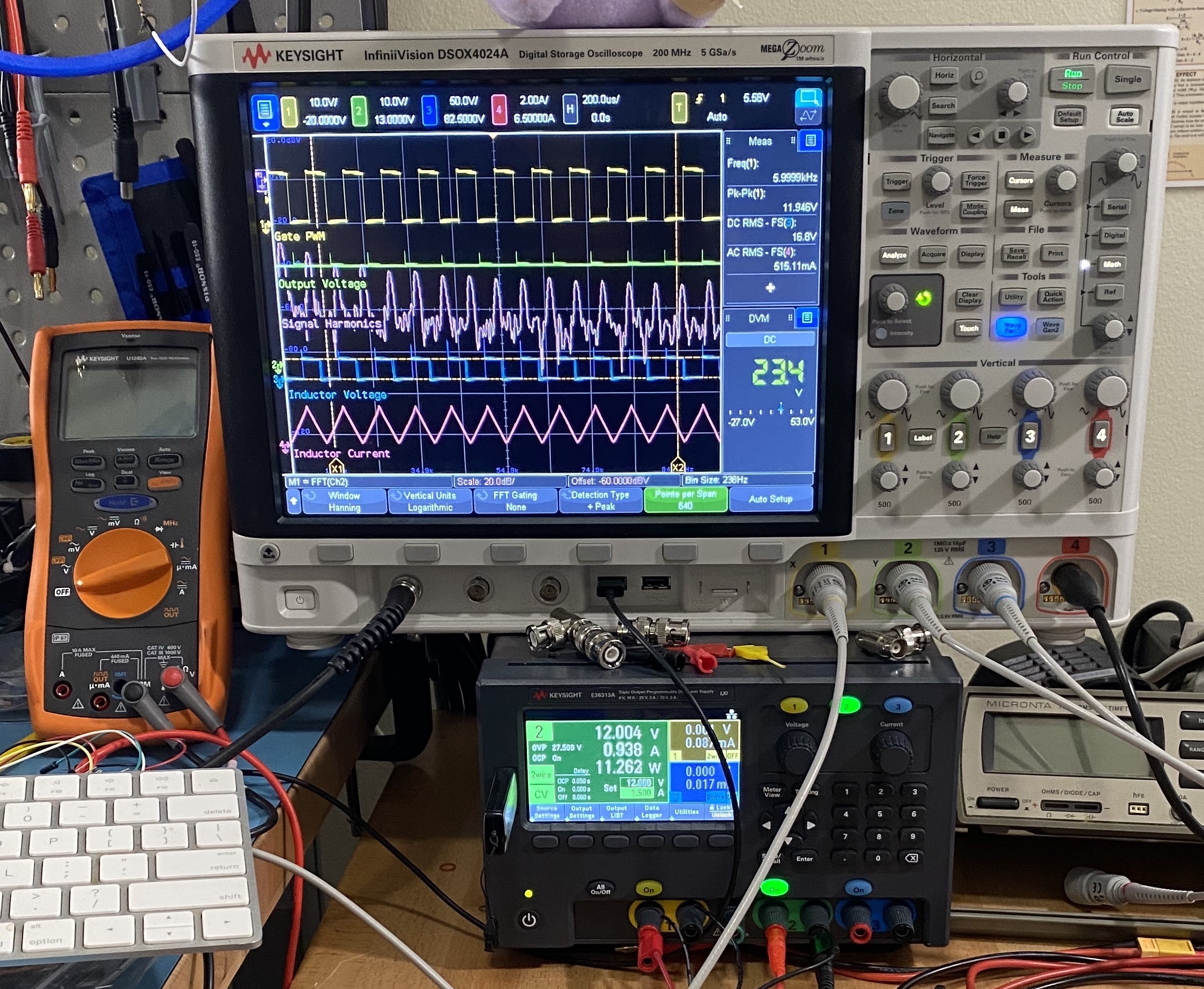
Image: Radarvector; source crop by Pittigrilli · Keysight InfiniiVision DSOX 4024A and digital multimeter and power supply in laboratory use · CC BY-SA 4.0. Existing source crop by Pittigrilli retained; no further image edits. Displayed at reduced size.

Engineering application and worked evidence
The following examples develop the display mechanisms and evidence decisions. Numerical values are teaching assumptions, not universal DO-160 limits. Use the adopted procedure for exact test conditions and the product requirements for functional acceptance.
An anomaly record preserves the event
An anomaly record should begin with what happened, when it happened and the conditions at that moment. Record the specimen, software, operating mode and applied exposure. Keep an observation such as a two-frame flash separate from a proposed cause such as cell deformation. Preserve raw data, photographs and logs before repeating the test. During investigation, document each configuration change and its purpose. Once the cause and correction are understood, agree the affected retest scope and update the requirement matrix. A later successful run adds evidence, but it does not remove the need to explain and disposition the original anomaly.
Basis: RTCA DO-160G, Section 3; authored qualification evidence practice. Retained reference in 80 Reference Library/Aerospace. Display mechanisms, design responses and worked cases are FPD.DEV engineering teaching synthesis, not additional DO-160 requirements. Numerical examples are illustrative.
A change-impact review across disciplines
Replacing a transparent heater can change more than cold performance. Its resistance and controller behaviour affect power demand. Its optical transmission and busbars affect the visible image. Its conductive structure can alter touch sensing and electromagnetic behaviour, and its bonding process can affect mechanical stress. Compare the old and new configurations against each relevant requirement and existing result. Document why an item remains covered or needs further evidence. A supplier's statement that the part is equivalent helps define the comparison but does not replace it. Close the review only when the resulting analysis, inspection or retest supports the revised assembly.
| Changed property | Potential effect | Evidence review |
|---|---|---|
| Resistance / control | Power and warm-up | Thermal and power tests |
| Conductive layer | Touch and EMC | Functional / EMC checks |
| Bonding / optics | Stress and transmission | Mechanical / optical checks |
Basis: RTCA DO-160G, Sections 4, 5, 8, 16, 20, 21 and 25; authored change case. Retained reference in 80 Reference Library/Aerospace. Display mechanisms, design responses and worked cases are FPD.DEV engineering teaching synthesis, not additional DO-160 requirements. Numerical examples are illustrative.
Practice: A heater substitution and retest scope
The new heater has the same nominal power but a different pattern, adhesive and busbar location. Create a change-impact record.
Model response and review points
Identify both configurations and the changed material and electrical properties. Review hot and cold thermal distribution, warm-up, power transients, optical transmission, touch operation, EMC and ESD current paths, mechanical stress and pressure behaviour. For every affected requirement, record the existing evidence, applicability rationale and added analysis, inspection or test. Assign closure ownership and preserve the anomaly and change history.
Page 18: Qualification-plan capstone
Qualification-plan capstone
DO-160 Display Qualification | A-P13 — Development edition
Learning objective: Assemble a reviewable plan and identify the inputs that prevent premature category selection.
Scenario — all values are teaching assumptions
You are buying a 10-inch bonded touch display with an internal LCD module, graphics processor, backlight, heater and metal enclosure. The complete assembly takes nominal 28 VDC; the panel uses an internal 5 V rail. The proposed installation is a pressurized flight-deck location with four structural mounts and conduction plus local airflow cooling. The customer asks for −40 °C to +70 °C operation, −55 °C to +85 °C unpowered survival, Section 5 Category B variation and a decompression test described only as 65,000 ft. No power-input, RF, lightning or vibration categories have been agreed.
The example intentionally contains incomplete allocations. Do not assume a Section 4 category from these numbers alone, and do not claim the proposed high-altitude endpoint is a universal DO-160 requirement.
Task 1 — define and question the boundary
Draw or describe the complete display architecture and supplied cables. Identify controlled interface simulators. List missing installation inputs: aircraft maximum operating altitude, pressure profile, local thermal environment, cooling failure conditions, vibration location, electrical power characteristics, shielding/bonding and functional criticality. State who must provide each input.
Task 2 — create the matrix
Consider Sections 4–26. For each applicable section give the candidate method and the information needed to finalize it. Use unresolved rather than a guessed category where input is missing. Document exclusions with a rationale. For the component panel, state which development data can support the complete-display plan and where it cannot.
Task 3 — write two procedure outlines
Prepare a cold-operation outline with explicit survival/conditioning separation, stabilization, timing and startup checks. Prepare a Section 5 outline using the complete adopted Category B sequence. Compute the ideal one-way −40 to +70 °C transition time at the minimum stated rate: 22 minutes. Identify the additional stages that prevent using 22 minutes as a total test duration.
For decompression, request initial and final absolute pressures, final altitude basis, transition time, hold, power/mode and acceptance. Explain the relationship between the proposed customer endpoint and the aircraft maximum operational altitude. Keep the Section 9 decision separate.
Task 4 — define monitoring and criteria
Write measurable requirements for startup, dynamic image continuity, luminance/contrast under defined conditions, controls, validity indications, resets and recovery. Classify each as during exposure, after exposure or survival. Specify synchronized observations and the uncertainty decision rule. Proposed numbers are design inputs until agreed; label them.
Task 5 — buy and hand over evidence
Prepare a deliverable list, configuration record, article allocation/sequence, deviation/retest process and installation-verification checklist. Include the source and report identifiers needed for another engineer to review every closed requirement. State any limits on evidence reuse for other panels, covers, touch controllers or harnesses.
Review rubric — 100 points
| Area | Points | Evidence of a strong submission |
|---|---|---|
| Boundary and missing inputs | 20 | Correct aircraft/internal interfaces; unresolved inputs have owners |
| Full-suite applicability | 20 | All 23 sections considered; justified allocations and exclusions |
| Temperature/pressure profiles | 20 | Correct state, stabilization, rate and timing distinctions |
| Functional acceptance and monitoring | 20 | Measurable display behavior with during/post criteria and uncertainty |
| Contract, evidence and installation | 20 | Traceable configuration, deliverables, retests and installed assumptions |
Suggested learning target: at least 80/100 and no unresolved misconception that survival proves operation, a component report qualifies the full assembly, or a chamber pass establishes installation approval. This is a teaching rubric, not an aviation qualification or personnel authorization.
Model-review highlights
A strong plan refuses to invent the missing power, vibration and lightning categories. It preserves the customer's temperature requests as explicit requirements while checking their relationship to Section 4. It treats 65,000 ft as a requirement needing clarification and reconciliation with the aircraft environment. It includes optical/control performance during the required exposures, a real configuration record and the integrator's installed-verification duties.
Second capstone case — helicopter installation
Now propose the same display for an assumed unpressurized helicopter, with an isolator-mounted instrument panel and a different harness route. This is a teaching scenario, not an AW139 specification. Do not carry over the first case’s pressurization, altitude, vibration, EMC or cooling assumptions without review.
- Ask the integrator for the aircraft model/configuration, intended location, mounting and bonding drawings, relevant rotational frequencies and blade counts, and measured local vibration data if available. Explain when the known-frequency, unknown-frequency or agreed tailored approach could be considered.
- Compare the new harness, shield terminations and bonds with the tested arrangement. Identify the evidence needed for equipment EMC, onboard compatibility, HIRF and lightning separately.
- Revisit pressure, temperature, water/dust exposure, power behavior and installed viewing/control use against the mission. Treat NVIS and gloved touch operation as explicit requirements when specified.
- Produce a two-application qualification matrix showing justified common evidence, additional work and unresolved inputs. Identify the contractual owner of each missing input.
Model-review point: “Use Category U2 and the highest RF category” is not an adequate answer. The method must fit the installation and intended coverage, while RF requirements depend on the function, environment and installation evidence. The existing 100-point rubric applies to either case; assess the aircraft-specific reasoning under boundary, applicability, monitoring and handover.
Additional integrator exercise
Identify one CTE mismatch, one trapped-air pocket and one vibration load path in your example. For each, state the mechanism, proposed control, configuration and observation needed to verify it. Explain why a passing final still image alone cannot close a transient-flash requirement.
Connection to the standards map
Extend the capstone to a military-aircraft variant. Prepare a standards-applicability map covering DO-160, tailored MIL-STD-810, equipment EMI, aircraft power and NVIS where invoked. Then identify what changes for a military ground-vehicle derivative. Choose one existing test report and document both supported credit and remaining gaps.
Page takeaway
- Submit the boundary, matrix, procedures, monitoring and installation/evidence package.
Supporting page images
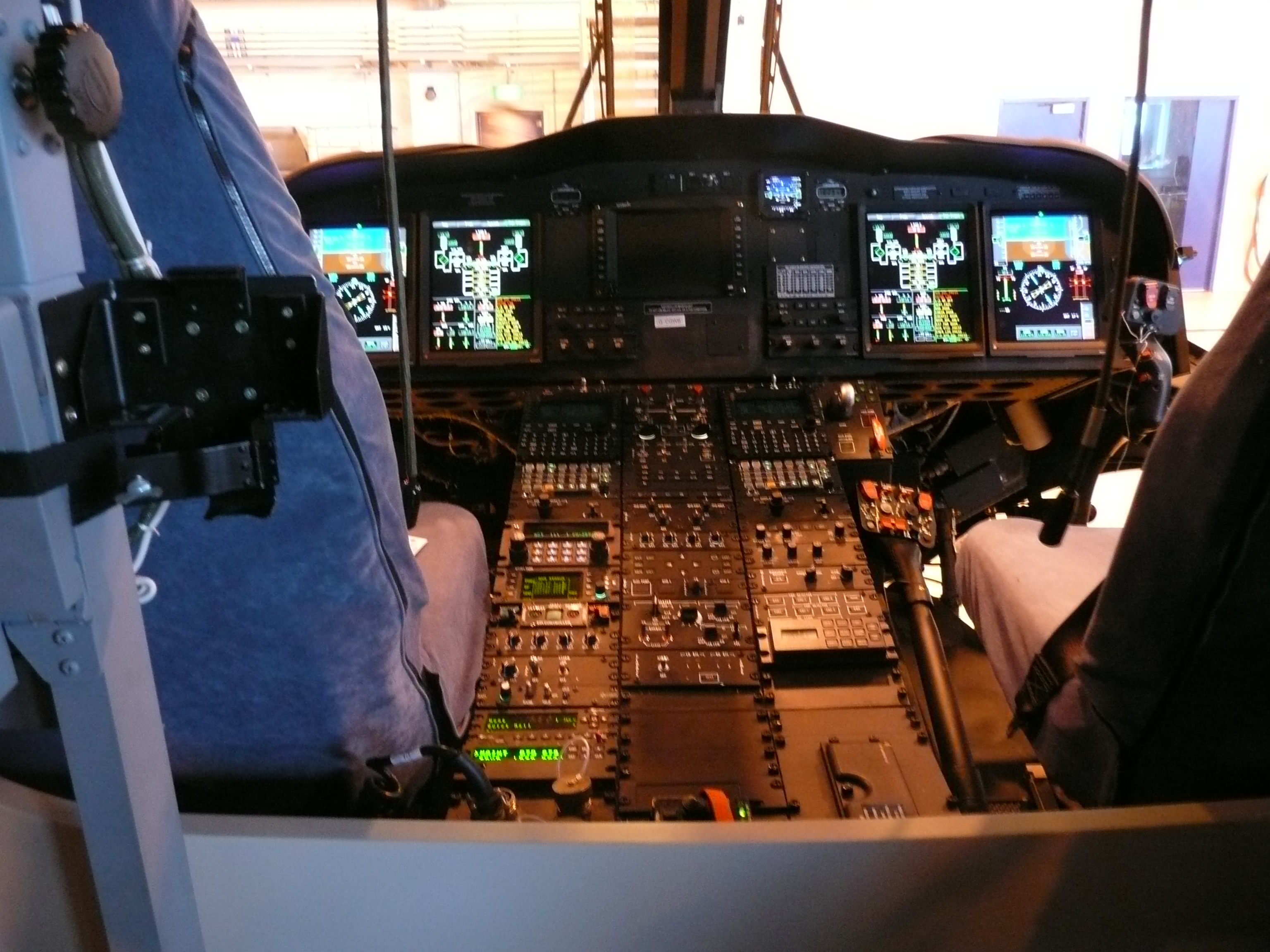
Photo: Terry Whalebone · AgustaWestland AW 139 helicopter cockpit · CC BY 2.0. Source image retained unchanged; displayed at reduced size.

Engineering application and worked evidence
The following examples develop the display mechanisms and evidence decisions. Numerical values are teaching assumptions, not universal DO-160 limits. Use the adopted procedure for exact test conditions and the product requirements for functional acceptance.
Capstone: a constrained design choice
For this capstone, assume a customer needs a readable cockpit display in bright ambient light, operation after cold soak, touch input and a fixed mounting envelope. The power budget limits heater and backlight demand. These are teaching assumptions rather than universal aviation requirements. Propose two optical and thermal configurations, then compare how each affects hot contrast, cold motion, power, EMC and mechanical behaviour. Identify the measurements needed to resolve the trade-off before choosing one. Record the uncertainties that remain and assign evidence to them. The exercise rewards a defensible decision and a coherent qualification plan, not simply the highest catalogue brightness.
Basis: RTCA DO-160G, Sections 4 through 25 as applicable; authored capstone. Retained reference in 80 Reference Library/Aerospace. Display mechanisms, design responses and worked cases are FPD.DEV engineering teaching synthesis, not additional DO-160 requirements. Numerical examples are illustrative.
Capstone review: what earns acceptance
Review the capstone as if you were accepting a supplier's qualification package. Can another engineer reproduce the test conditions and understand the decision? Does the hot-contrast claim include ambient illumination and panel temperature? Does the cold case address moving information and warm-up? Do the power and susceptibility cases include valid data and unintended commands? Check that changes to the optical stack connect to mechanical and electrical evidence. List unresolved items with an owner and a specific closure condition. A justified open item is preferable to an unsupported pass. Use the model response in the reading page to challenge your own reasoning.
Basis: RTCA DO-160G, Sections 3 through 25 as applicable; authored capstone review. Retained reference in 80 Reference Library/Aerospace. Display mechanisms, design responses and worked cases are FPD.DEV engineering teaching synthesis, not additional DO-160 requirements. Numerical examples are illustrative.
Practice: Capstone model response and review rubric
Prepare two candidate display stacks for the constrained cockpit example. Deliver a requirements matrix, trade study, monitoring plan, specimen/sequence plan and one completed illustrative anomaly record. Spend 20–30 minutes before opening the model response.
Model response and review points
A strong response first defines the installation assumptions and measurable functions. Candidate A might use lower reflection and moderate backlight power. Candidate B might rely on higher backlight power with a different thermal design. These are options to investigate, not predetermined winners. Compare measured or planned Hot Contrast, cold response, spectrum, touch, power and thermal margins, then EMC, mechanical and pressure effects. Select applicable categories from the controlled requirements rather than guessing them. The monitoring plan needs synchronized image, data-validity and command evidence. The test matrix names configuration, method, state, acceptance rule and evidence owner for every row. The specimen plan retains exposure and repair history. The anomaly record separates observation, cause, correction and verification. Review each deliverable for completeness and technical reasoning. Unsupported numerical limits or an unexplained not-applicable decision remain open items.
Page 19: Knowledge check and review
Knowledge check and review
DO-160 Display Qualification | A-P13 — Development edition
Learning objective: Check the key distinctions before reviewing the capstone.
Complete the 14 knowledge questions
Answer all 14 questions before opening their explanations. Review incorrect answers, then review the capstone against its rubric. These questions support learning; platform completion rules are separate. No aviation approval or personnel certification follows from this quiz.
If you miss a question about boundaries, survival versus operation, category meaning or decompression, return to the public foundations. For EMC, lightning or configuration-change questions, revisit the corresponding method lesson and identify the missing evidence in your own matrix.
Materials and mounting review
Explain CTE, distinguish adhesive from cohesive failure, and describe why adding a soft mount does not automatically reduce vibration at every frequency.
Worked response
CTE describes fractional dimensional change per degree. Adhesive failure occurs at an interface; cohesive failure occurs within a material. A passive mounting system can amplify motion near resonance, so verify the complete assembly against the applicable excitation and image/retention criteria.
Additional standards questions
Can a high-temperature storage pass automatically satisfy a powered operating-temperature requirement?
Answer
No. Compare configuration, complete exposure and powered functional acceptance; record supported credit and remaining gaps.
Which standards distinguish equipment EMI from system electromagnetic effects?
Answer
MIL-STD-461 addresses equipment/subsystem EMI; MIL-STD-464 addresses system E3. Apply the actual allocated requirements.
Page takeaway
- Use the feedback to correct the matrix and capstone; a course score does not establish aviation approval.
Knowledge check and discussion
1. Does a bare LCD temperature report qualify the complete aircraft-powered display?
- Yes, if resolution is unchanged
- No; assess component credit and qualify the complete boundary
- Yes, if the panel survived +85 °C
Show answer and explanation
No; assess component credit and qualify the complete boundary
The complete assembly adds power, enclosure, cooling, touch, wiring and functional behaviors.
2. What does DO-160G Category X record?
- Compliance was not demonstrated
- The most severe category was passed
- The condition is automatically inapplicable
Show answer and explanation
Compliance was not demonstrated
Applicability needs its own rationale; X is not a passing result.
3. Which Section 5 minimum ramp rate corresponds to Category B?
- 2 °C/min
- 5 °C/min
- 10 °C/min
Show answer and explanation
5 °C/min
In DO-160G Section 5, A/B/C correspond to minimum 10/5/2 °C per minute.
4. How long is an ideal −40 to +70 °C one-way transition at 5 °C/min?
- 11 minutes
- 22 minutes
- Two hours including stabilization
Show answer and explanation
22 minutes
110 °C divided by 5 °C/min is 22 minutes; dwells and other stages are additional.
5. What does an unpowered +85 °C survival result establish?
- Continuous readable operation at +85 °C
- The applicable survival evidence, subject to its criteria
- All temperature categories
Show answer and explanation
The applicable survival evidence, subject to its criteria
Survival does not demonstrate a separate powered operating requirement.
6. Is 65,000 ft the universal DO-160G decompression endpoint?
- Yes
- Only for touch displays
- No; the method and aircraft/customer allocation define the endpoint
Show answer and explanation
No; the method and aircraft/customer allocation define the endpoint
Section 4.6.2 refers to aircraft maximum operational altitude; a customer profile must be explicit.
7. What does Section 9 explosion proofness address?
- Ignition in a flammable atmosphere
- The speed of every pressure decompression
- A universal display-glass impact test
Show answer and explanation
Ignition in a flammable atmosphere
Rapid decompression is a pressure topic in Section 4, not Section 9.
8. Why is a static logo a weak functional monitor during EMC testing?
- It consumes too much power
- It can conceal a frozen frame
- It invalidates every emissions measurement
Show answer and explanation
It can conceal a frozen frame
A dynamic sequence and timed monitoring can detect a freeze that a static image hides.
9. What is missing from the claim Lightning Level 3?
- Nothing for any cockpit installation
- Only the display diagonal
- Applicable waveforms/methods, configuration and installation allocation
Show answer and explanation
Applicable waveforms/methods, configuration and installation allocation
The headline level is not a complete test specification or aircraft compliance argument.
10. After a touch-controller change, what is the best evidence approach?
- Reuse every old report automatically
- Assess affected mechanisms and substantiate credit or retest
- Repeat only a room-temperature image check
Show answer and explanation
Assess affected mechanisms and substantiate credit or retest
Changes can affect EMI, ESD, power and controls; the assessment determines regression scope.
11. Does laboratory qualification alone establish installed readability?
- No; viewing geometry, lighting and installation must be verified
- Yes, if the panel is bright
- Yes, if every category letter is listed
Show answer and explanation
No; viewing geometry, lighting and installation must be verified
Installed viewing and operating assumptions need their own evidence.
12. Which contract deliverable best supports an independent review?
- A single pass certificate
- Only the laboratory invoice
- Configuration, as-run records, data, anomalies/retests, report and qualification summary
Show answer and explanation
Configuration, as-run records, data, anomalies/retests, report and qualification summary
Traceable underlying evidence is needed to understand what was demonstrated.
13. Can a MIL-STD-810 high-temperature storage pass automatically satisfy a DO-160 operating-temperature requirement?
- Yes, if its maximum temperature is higher
- No; compare purpose, configuration, exposure and powered acceptance
- Yes, if the display part number matches
Show answer and explanation
No; compare purpose, configuration, exposure and powered acceptance
Storage and powered operation require different evidence. Document supported credit and test remaining gaps.
14. Which pair best separates equipment EMI from system electromagnetic environmental effects?
- MIL-STD-461 and MIL-STD-464
- MIL-STD-810 and MIL-STD-3009
- DO-178C and IEC 60529
Show answer and explanation
MIL-STD-461 and MIL-STD-464
MIL-STD-461 addresses equipment/subsystem EMI; MIL-STD-464 addresses system E3. Their exact allocated requirements depend on the program.
Practice: Evidence-based final review
Choose one environmental, one power and one EMC claim from your own product. Explain what would make each claim reproducible and what could invalidate its evidence after a change.
Model response and review points
Each claim needs a requirement source, applicable method and category, controlled specimen and installation boundary, operating mode, measurable acceptance and linked result. Identify actual observed behaviour during exposure and after recovery. Explain the change-sensitive features such as optical stack, heater, mount, shielding or software. A result without a configuration or decision rule does not establish a complete qualification claim. Use the existing knowledge questions as a check, then revisit the worked cases where your evidence is incomplete.
References and sources
- FAA AC 21-16G, §§4 and 7: DO-160 environmental qualification and regulatory context
- MIL-STD-810H Change 1, Part One and selected Part Two methods: MIL-STD-810 tailoring
- MIL-STD-461, scope and invoked test methods: Equipment EMI
- MIL-STD-464, scope: System E3
- MIL-STD-704 and MIL-HDBK-704 series, scope: Aircraft power
- MIL-STD-1275, scope: Military ground-vehicle power
- MIL-STD-3009, scope: NVIS display emission
- MIL-STD-1472, scope: Human engineering
- FAA AC 20-115D, DO-178C / ED-12C: Airborne software assurance
- FAA AC 20-152A, DO-254 / ED-80: Airborne electronic hardware assurance
- SAE ARP4754B, publisher scope; program adoption separately established: Aircraft and system development
- SAE ARP4761A, publisher record; program adoption separately established: Aircraft safety assessment
- SAE AS8034C, publisher scope; use the actually invoked revision: Airborne display performance
- www.faa.gov: FAA AC 20-158B
- www.faa.gov: FAA AC 20-136C
- saemobilus.sae.org: SAE AS8034 publisher entry
- www.faa.gov: FAA AC 20-136C
- my.rtca.org: RTCA Environmental Qualification Form
This course is a living document. Enrolled learners typically receive updates when chapters are revised. Use your project’s adopted standards and qualification baseline.
There are no comments for now.
to be the first to leave a comment.